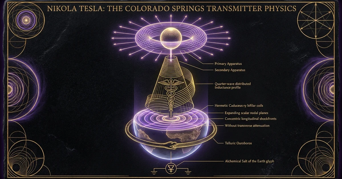
Nikola Tesla: The Colorado Springs Transmitter Physics
Executive Summary & Theoretical Thesis
The Hertzian Paradigm versus Bound Terrestrial Conduction
The conceptual divergence between Nikola Tesla and mainstream late-nineteenth-century electrodynamics hinges upon the operational definition of electromagnetic propagation. Following Heinrich Hertz’s 1888 experimental confirmation of Maxwellian transverse waves, the emerging telecommunications consensus established that high-frequency electromagnetic energy propagates through space via transverse electromagnetic (TEM) waves. In this orthodox framework, field vectors $\mathbf{E}$ and $\mathbf{B}$ are orthogonal to each other and perpendicular to the direction of wave propagation $\mathbf{k}$, distributing radiative energy density across an expanding spherical wavefront whose power flux dissipates asymptotically following the inverse-square law:
$$S® = \frac{P_{\text{rad}}}{4\pi r^2}$$
Tesla recognized this radiation mode as inherently dissipative and inefficient for macro-scale power transmission. In his fundamental critique, detailed throughout The Problem of Increasing Human Energy (Tesla, 1900), Tesla classified Hertzian waves as energetic leakage—unbound radiative emission escaping into free space without systemic recovery mechanisms.
To bypass this geometric dissipation, Tesla’s engineering paradigm centered on bound terrestrial conduction, viewing the earth-ionosphere system not as empty space through which unguided waves migrate, but as an energetic substrate capable of supporting forced electrical oscillations. The Colorado Springs experimental apparatus, documented in U.S. Patent No. 1,119,732 (Apparatus for Transmitting Electrical Energy, 1914), abandoned electromagnetic radiation in favor of electrodynamic displacement currents. Rather than using an oscillating dipole to shed power into the upper atmosphere, Tesla designed a high-voltage, low-frequency apparatus that injected rhythmic volumetric displacement currents directly into the lithosphere. This transformed the earth from a passive electrical ground into an active, resonant conductor wherein charge oscillates as a unified standing wave system.
The Magnifying Transmitter as a Distributed Resonator
The structural foundation of the Colorado Springs design is the Magnifying Transmitter, an apparatus fundamentally distinct from standard two-winding air-core or iron-core transformers. The operational engine consists of a three-element resonant architecture: a low-inductance, heavy-copper primary winding driven by a high-voltage condenser bank; an intermediate secondary winding wound in close proximity to induce significant initial voltage rise; and an autonomous, free-standing helical inductor designated as the “extra coil.” This extra coil functions as a distributed-constant cavity resonator rather than a lumped-element inductive choke.
By physically segregating the extra coil from the primary-secondary assembly, Tesla suppressed mutual inductive damping between the spark gap driver and the elevated resonator. The extra coil was engineered specifically as an asymmetric slow-wave structure. Within this helical architecture, the spatial phase velocity of the electrical wave traveling along the conductor axis is compressed, while the linear wire velocity matches the speed of light:
$$v_p \ll c$$
The base of the extra coil establishes an electrical current anti-node (voltage node) bonded through deep-well grounding plates directly into the moist telluric bedrock of Colorado Springs. The top end terminates at a hollow copper sphere mounted atop a 142-foot mast, forming a spatial voltage anti-node (current node). This structural boundary allows the coil to resonate strictly at a quarter-wavelength ($\lambda/4$) mode, converting large circulating primary currents into localized dielectric stress potentials exceeding twelve million volts without flashover to the primary tank circuits.
The Telluric Current Reservoir and Quarter-Wave Boundary Dynamics
The true operational medium of the Magnifying Transmitter is the planet’s endogenous electrostatic charge reservoir. Classical transmission engineering treats ground connections as infinite charge sinks governed by the Poisson-Laplace condition $\nabla^2 V = 0$. Tesla inverted this assumption by treating the Earth as a finite, spherical conducting boundary characterized by intrinsic capacitance:
$$C_{\oplus} = 4\pi \varepsilon_0 R_{\oplus} \approx 708,\mu\text{F}$$
When the extra coil operates at its fundamental quarter-wave resonance, it exerts a microscopic push-pull effect on this planetary charge reservoir. The mechanical analog is that of an acoustic piston coupled to an expansive hydraulic chamber. The terminal sphere generates an intense dielectric field, but because its effective radiation resistance:
$$R_{\text{rad}} = 80\pi^2 \left(\frac{h}{\lambda}\right)^2$$
is kept negligible via long operational wavelengths ($\lambda \approx 10^3$ to $10^4\text{ km}$), transverse radiation leakage drops toward zero. The kinetic electrical displacement is redirected entirely into the terrestrial substrate, establishing alternating /physics-electromagnetism/longitudinal-dielectric-displacement waves.
These telluric currents propagate through the crust and mantle via pure electrostatic displacement and electronic drift, guided by the conductive lithosphere and bounded above by the dynamic ionospheric sheath. By tuning the primary oscillation frequency to an exact subharmonic or harmonic of the terrestrial electrical transit time, the apparatus establishes macroscopic stationary nodes across the globe, allowing energy extraction via syntonized secondary receivers without inverse-square spatial attenuation.
Within a tightly wound helical resonator such as Tesla’s extra coil, the axial propagation velocity $v_w$ of the electromagnetic wave along the longitudinal axis of the cylinder is severely retarded relative to the free-space speed of light $c$. This spatial phase deceleration is governed by the structural pitch, the coil diameter, and the inter-turn dielectric geometry. According to the empirical and transmission-line formalisms validated by Corum and Corum (1989), the slow-wave propagation velocity factor within uniform single-layer solenoids is formulated as:
$$v_w = \frac{c}{\sqrt{1 + 20 \left(\frac{D}{s}\right)^{2.5}}}$$
where $D$ represents the coil diameter, and $s$ represents the turn-to-turn winding spacing (center-to-center pitch). Consequently, when the ratio $D/s$ is large, the effective axial velocity drops substantially, permitting a physically compact coil to accommodate an electrical quarter-wavelength ($\lambda/4$) matching wavelengths of hundreds of kilometers. This deceleration isolates the elevated terminal at an absolute spatial voltage anti-node, driving the scalar-potential to extremes while keeping radiated transverse fields suppressed.
Historical Lineage & Experimental Precedents
The Houston Street Laboratory Precursors and Limitations
Before establishing the Colorado Springs installation in May 1899, Tesla conducted extensive investigations into high-potential, high-frequency physical dynamics at his 35 South Fifth Avenue and 46 East Houston Street laboratories in New York City. These urban facilities highlighted the engineering limits of lumped-element transformer geometries. In these early iterations, the secondary winding of the oscillating transformer was wrapped concentrically inside or directly above the primary winding. As Tesla increased the applied potential beyond one million volts, the proximity of the primary turns created catastrophic dielectric breakdown across the air gaps and insulation barriers. The intense electrostatic field ionized the air surrounding the coils, precipitating corona discharges, inter-turn arcing, and heavy dielectric losses that disrupted system resonance.
Furthermore, the mutual inductance $M$ between tightly coupled primary and secondary circuits imposed an unwanted operational compromise. The high resistance of the primary discharge path—specifically the continuous resistance of the electric arc within the mechanical spark gap—imposed heavy mutual damping upon the secondary resonator. This primary-secondary damping clamped the system’s quality factor ($Q$) to modest values below 100, capping the maximum achievable voltage rise:
$$V_{\text{out}} = Q \cdot V_{\text{in}}$$
The limited physical clearance of the Houston Street laboratory prevented Tesla from erecting structures capable of operating at wavelengths exceeding a few kilometers. He was also unable to establish true ground-wave coupling due to the interfering labyrinth of New York City’s underground water pipes, gas lines, and structural foundations, which acted as parasitic capacitances that dispersed his high-frequency currents.
Houston Street (Coupled Dual-Coil)          Colorado Springs (Decoupled Triple-Coil)
                 +-----------+                                 +-----------+
                 | Spark Gap |                                 | Spark Gap |
                 +-----+-----+                                 +-----+-----+
                       |                                             |
            +----------+----------+                       +----------+----------+
            | Primary / Secondary |                       | Primary / Secondary |
            |  Concentric Forms   |                       | Loosely Coupled Base|
            +----------+----------+                       +----------+----------+
                       |                                             |
            [ Severe Mutual Damping ]                                +-----> [ Isolated Extra Coil ]
            [ Terminal Breakdown    ]                                        [ Resonant Voltage Step]
            [ Low System Q (<100)   ]                                        |
                                                                             +-----> [ Elevated Terminal ]
                                                                             |
                                                                    [ High System Q (>1000) ]
                                                                    [ Terrestrial Injection ]
Site Selection at Colorado Springs: High Altitude and Telluric Baseline
Tesla chose the plateau of Colorado Springs, Colorado (altitude approximately 6,000 feet above sea level), based on physical parameters critical to extreme electrodynamic experimentation. The elevated altitude yielded a significant reduction in atmospheric pressure ($\approx 600\text{ mm Hg}$ compared to $760\text{ mm Hg}$ at sea level). In accordance with Paschen’s Law, the breakdown voltage of air varies non-linearly with pressure and gap distance:
$$V_B = \frac{B \cdot p \cdot d}{\ln(A \cdot p \cdot d) - \ln\left[\ln\left(1 + \frac{1}{\gamma_{\text{se}}}\right)\right]}$$
While this reduced pressure lowered the local breakdown threshold for thin wires, Tesla turned it to his advantage on large-radius conductive geometries. By employing large-diameter, smooth spherical terminals, he prevented premature local ionization, while the rarefied surrounding air accommodated vast non-arcing dielectric displacements at the mast’s zenith.
Geographically, Colorado Springs sat adjacent to Pikes Peak, an area of high telluric electrical activity and severe orographic thunderstorms. The soil composition—predominantly decomposed Pikes Peak granite overlaid by dry topsoil with localized pathways to subterranean water tables—presented unique electrical characteristics. The dry surface layer formed a dielectric buffer that forced currents injected into the deep well plates to spread horizontally into the conductive regional aquifers.
Most importantly, the region offered an undisturbed electrodynamic canvas. Free from industrial electromagnetic interference, Tesla could monitor transient perturbations in the earth’s natural electrostatic field caused by lightning strikes moving across the Colorado plains.
Experimental Evolution of the 1899 Oscillating Plant
Between June 1899 and January 1890, the Colorado Springs laboratory evolved from an experimental shed into a dedicated mega-volt oscillator. The structure featured an 80-foot square wooden building built without ferrous metals near the operational coils to prevent eddy current damping. At the center sat the Magnifying Transmitter’s primary-secondary platform. The primary consisted of an open-air, single-turn (later two-turn) circular fence of heavy stranded cable 51 feet in diameter, fastened directly to the floor. Concentric with this primary, an open-frame secondary of 48 turns of rubber-insulated wire rose on structural wood uprights.
“Observations made July 3, 1899: In the course of these experiments, performed with the apparatus for the production of powerful electrical oscillations, a phenomenon of unusual character was observed… When the source of the electrical disturbances was at a distance of about 60 miles, the apparatus responded strongly, but as the storm moved further away, the signals became stronger and stronger, reaching a maximum when the storm was at a distance of about 120 miles. Continuing its retreat, the storm produced vibrations which gradually diminished in intensity, then ceased entirely, only to reappear again at a distance of 180 miles… These observations demonstrated beyond a doubt that the electrical waves produced by the discharges were stationary waves, possessing nodes and antinodes, and proved that the earth, despite its great dimensions, behaves as a conductor of limited dimensions.”
The definitive architectural breakthrough occurred when Tesla decoupled the third coil—the extra coil—from this primary-secondary foundation. Positioned away from the main primary loop, this upright cylindrical inductor measured 8.3 feet in diameter and 10 feet in height, wound with heavy wire optimized for lowest internal high-frequency resistance. By adjusting the turn-to-turn spacing, Tesla altered the inter-turn capacitance, tuning the coil’s natural propagation velocity. The apparatus was powered by a 50,000-volt Westinghouse utility transformer fed from the local municipal grid, switched through customized rotary and liquid-quenched spark interrupters capable of breaking thousands of amperes at precisely indexed phase angles.
Mathematical Formalism & Physical Mechanics
Distributed Transmission Line Equations for the Extra Coil
The extra coil cannot be characterized as a simple lumped inductor ($L$) with a parasitic self-capacitance ($C$). Because the operational physical wire length $l$ approaches a significant fraction of the resonant electrical wavelength ($\lambda/4$), the structure behaves as a true non-uniform transmission line with distributed parameters: series inductance per unit length $L_0$, shunt capacitance per unit length $C_0$, series resistance $R_0$, and shunt conductance $G_0$. The voltage and current distributions along the axial height $z$ of the coil are governed by the rigorous telegrapher equations:
$$-\frac{\partial V(z, t)}{\partial z} = R_0 I(z, t) + L_0 \frac{\partial I(z, t)}{\partial t}$$
$$-\frac{\partial I(z, t)}{\partial z} = G_0 V(z, t) + C_0 \frac{\partial V(z, t)}{\partial t}$$
For time-harmonic oscillations at angular frequency $\omega = 2\pi f$, the spatial voltage distribution along the extra coil of length $l$ is expressed as a superposition of incident and reflected hyperbolic wave vectors:
$$V(z) = V_L \cosh(\gamma z) + I_L Z_0 \sinh(\gamma z)$$
where the complex propagation constant $\gamma = \alpha + j\beta = \sqrt{(R_0 + j\omega L_0)(G_0 + j\omega C_0)}$ defines both the attenuation factor $\alpha$ and the spatial phase constant $\beta$. The characteristic impedance $Z_0$ of the helical line is formulated as:
$$Z_0 = \sqrt{\frac{R_0 + j\omega L_0}{G_0 + j\omega C_0}} \approx \sqrt{\frac{L_0}{C_0}}$$
In the loss-minimized state engineered by Tesla ($\alpha \to 0$), the condition of quarter-wave resonance dictates that the electrical length fulfills $\beta l = \pi/2$. At the grounded base ($z = 0$), the boundary condition exhibits a low impedance approaching a short circuit ($V(0) \approx 0, I(0) = I_{\text{max}}$). At the ungrounded top ($z = l$), terminated into the elevated isotropic capacitance of the terminal sphere $C_{\text{term}}$, the impedance approaches an open circuit. This produces an extreme standing-wave-ratio (SWR), concentrating the scalar-potential at the terminal sphere:
$$V(l) = -j I_{\text{base}} Z_0$$
Because $Z_0$ for a tall, slender helical resonator often ranges from $1,000,\Omega$ to $5,000,\Omega$, a modest base drive current of 200 amperes forces the terminal potential past millions of volts:
$$|V(l)| = 200 \times 5,000 = 1,000,000\text{ V}$$
Coupling Coefficients and Mutual Inductance Decoupling
In standard resonant transformers, the magnetic coupling coefficient $k$ between the primary winding ($L_p$) and the secondary winding ($L_s$) is defined via mutual inductance $M$:
$$k = \frac{M}{\sqrt{L_p L_s}}$$
If $k$ approaches unity (tight coupling), the phenomenon of resonant frequency splitting occurs. The system’s single operational mode bifurcates into two distinct frequency peaks:
$$\omega_{1,2} = \frac{\omega_0}{\sqrt{1 \pm k}}$$
This splitting bleeds energy away from the fundamental resonant frequency, rendering sustained single-frequency planetary excitation impossible.
Tesla solved this by enforcing two deliberate architectural boundaries:
- The primary-to-secondary stage operated under loose coupling ($k < 0.15$), mitigating primary arc-damping feedback and mode-splitting.
- The extra coil was physically removed from the inductive field of the primary-secondary assembly ($k_{\text{extra-primary}} \to 0$).
With mutual inductance eliminated between the extra coil and the spark gap, the extra coil acted as an isolated energy reservoir whose operational quality factor $Q$ was governed exclusively by its own copper geometry and radiant dielectric losses:
$$Q_{\text{extra}} = \frac{\omega L_{\text{extra}}}{R_{\text{effective}}} > 1,000$$
Energy transferred from the secondary into the base of the extra coil via direct galvanic conduction at a precise spatial phase match. This injected pure active power directly into the distributed line, bypassing the heavy resistive losses of the primary discharge circuit.
Global Boundary Conditions and Stationary Wave Formulations
To conceptualize the macroscopic wave mechanics initiated by the Colorado Springs apparatus, the Earth must be mathematically formulated as a bounded, conducting sphere of radius $R_{\oplus} \approx 6,371\text{ km}$, bounded internally by core conductivity and externally by the ionosphere at height $h \approx 60\text{–}100\text{ km}$. The wave equation for the magnetic vector potential $\mathbf{A}$ and the scalar-potential $\Phi$ in a source-free, radially symmetric spherical coordinate system $(r, \theta, \phi)$ derived from Maxwell-Heaviside equations is:
$$\nabla^2 \Phi - \mu_0 \varepsilon_0 \frac{\partial^2 \Phi}{\partial t^2} - \mu_0 \sigma \frac{\partial \Phi}{\partial t} = 0$$
Under localized, point-source alternating current injection $I(t) = I_0 e^{j\omega t}$ anchored at the terrestrial origin ($\theta = 0$, Colorado Springs), the boundary condition at the surface ($r = R_{\oplus}$) can be decomposed into an infinite series of spherical harmonics employing Legendre polynomials $P_n(\cos\theta)$:
$$\Phi(\theta, t) = \sum_{n=0}^{\infty} A_n P_n(\cos\theta) e^{j\omega t}$$
The dynamic solution manifests as a stationary surface wave where current and voltage components oscillate out of phase by 90 degrees. Tesla’s physical objective was to tune the operational driving frequency $\omega$ such that the antipode of the injection point ($\theta = \pi$, situated in the Indian Ocean near the Îles Amsterdam and Saint-Paul) formed an absolute voltage anti-node. The wavelength of this fundamental planetary stationary mode satisfies the boundary geometry:
$$\lambda_0 \approx 2\pi R_{\oplus} \approx 40,000\text{ km}$$
yielding a theoretical fundamental base frequency:
$$f_0 = \frac{c}{\lambda_0} \approx \frac{3 \times 10^8\text{ m/s}}{4 \times 10^7\text{ m}} \approx 7.5\text{ Hz}$$
By exciting these harmonics at higher order modes ($f_n = n \cdot f_0$, typically between 1 kHz and 30 kHz), the transmitter set up stationary nodelines across the lithosphere. The mathematical verification of this telluric standing wave profile is defined by the nodal zeroes of the zero-order spatial Legendre function:
$$P_n(\cos\theta) = 0$$
creating permanent, spatially coherent rings of non-attenuating /physics-electromagnetism/schumann-resonance-planetary-harmonics across the planet’s surface.
Empirical Evidence & Observational Data
Primary Data Logs: The July 1899 Lightning Influx Signatures
Tesla’s confirmation of terrestrial electrical resonance occurred during his systematic analysis of severe regional cyclonic storms in early July 1899. Using sensitive receiving coherers coupled to broad-aperture inductive pick-up circuits and specialized high-pass telluric grounding terminals, he monitored the high-frequency reverberations caused by massive atmospheric lightning discharges.
As individual lightning events struck the front ranges of Colorado, they injected high-energy, broad-spectrum impulses into the earth’s crust. If the lithosphere functioned merely as an infinite, dissipative electrical ground sink, the magnitude of the detected signals would decay monotonically as the lightning cell retreated east across the plains:
$$\lim_{r \to \infty} |\mathbf{E}®| = 0$$
The empirical recordings logged across the Colorado Springs Notes (July 3 through July 13, 1899) disproved monotonic decay. The detected coherer response displayed pronounced, periodic oscillations between absolute signal nulls and distinct local maxima.
As the storm front moved hundreds of kilometers away, the instrument swept through alternating nodes and anti-nodes. By tracking the distance to the storm through optical lightning detection and acoustic delay intervals, Tesla measured the spatial distance between the resulting nodes. This provided experimental proof that the terrestrial sphere was acting as an isolated cavity resonator capable of supporting macro-scale stationary wave patterns.
Signal Intensity (E-field)
  ^
  │      Peak (Anti-Node)            Peak (Anti-Node)
  │         /\                          /\
  │        /  \                        /  \
  │       /    \                      /    \
  │      /      \                    /      \
  │─────/────────\──────────────────/────────\──────────> Distance (r)
  │               \      Node      /          \
  │                \      │       /            \
  │                 \_____│______/              \_______
  │
  0               Node 1 (Zero)              Node 2 (Zero)
Distance Scaling: Field Induction across 26 Miles
Having observed lightning-driven standing waves, Tesla sought to recreate the phenomenon artificially. Driving his primary-secondary circuit into continuous high-power excitation, he operated the Magnifying Transmitter at power levels between 20 and 50 kilowatts, cycling at operational frequencies measured between 10 kHz and 50 kHz.
To determine field distribution and confirm power transmission via telluric currents, Tesla dispatched his assistant, Fritz Lowenstein, with portable receiving apparatuses across the surrounding El Paso County terrain. At a calibrated testing station erected approximately 26 miles (41.8 kilometers) away from the laboratory, an independent resonant receiving circuit was grounded into the earth with an elevated terminal mounted to collect local displacement fields.
Without any direct metallic wiring or line-of-sight Hertzian dipole beam paths, the receiving station extracted sufficient electrical energy from the earth’s surface to light multiple incandescent filament bulbs. The spatial distribution of this energy extraction adhered strictly to tuned syntony: detuning the receiver’s variable inductor by a fraction of a percent caused the lamps to extinguish completely. This proved that energy reception was governed by high-$Q$ /sound-cymatics/acoustic-levitation-standing-waves operating within the dielectric medium rather than broadband electromagnetic induction.
Modern Laboratory Replications and Corum Measurements
For nearly a century, orthodox engineering literature dismissed Tesla’s Colorado Springs standing wave logs as misinterpretations of near-field induction effects or instrumentation artifacts. However, beginning in the 1980s, high-voltage physicists Kenneth L. Corum and James F. Corum performed detailed laboratory replications and mathematical re-analyses of Tesla’s original apparatus using modern vector network analyzers and RF instrumentation.
Corum, K. L., and Corum, J. V. (1989). “Disclosures Concerning the Operation of an ELF Oscillator,” Proceedings of the International Tesla Symposium. The Corum measurements proved that Tesla’s extra coil does not function as an elementary lumped-element coil or as an electric dipole antenna. Rather, it operates strictly as a slow-wave helical transmission line resonator exhibiting an operational loaded quality factor:
$$Q_L > 1,500$$
Their experimental findings proved that the radiated transverse electromagnetic field of this geometry is suppressed:
$$P_{\text{rad}} < 0.01 \times P_{\text{stored}}$$
This confirms that the extra coil acts as an exceptional reactive electrostatic energy reservoir, operating as a slow-wave cavity resonator matching Tesla’s structural descriptions.
The Corum experiments confirmed that single-layer, open-geometry solenoids whose heights and diameters match the physical proportions documented in Tesla’s July 1899 patent applications exhibit an acoustic-like, non-radiating standing wave mode. In this mode, the phase velocity factor drops dramatically, satisfying the quarter-wave resonance conditions required to produce boundary-wave conduction without generating the high radiation resistance losses typical of Hertzian antennas.
Metaphysical Implications & Unified Synthesis
The Dynamic Ether and Dielectric Stress Geometries
Tesla’s physical cosmology rejected the emerging post-Newtonian and Einsteinian frameworks that treated space as an empty, geometric vacuum curved by localized gravitational masses. Drawing from the classical hydrodynamic ether models of William Thomson (Lord Kelvin) and J.J. Thomson, Tesla conceptualized the physical universe as an infinite, incompressible, non-particulate fluid: the luminiferous ether. In this worldview, matter does not exist as an independent entity inhabiting a void; rather, all physical forms are standing geometric vortices dynamically sustained within this underlying etheric substrate.
Within this framework, electric charge represents an active localized state of etheric rotation, and the dielectric field describes an elastic spatial strain tensor:
$$\mathcal{T}{ij} = \varepsilon \left( E_i E_j - \frac{1}{2}\delta{ij} E^2 \right)$$
impressed upon this medium. Electrostatic potential differences do not signify a disparity of physical particles accumulated at discrete terminals, but rather localized gradients of etheric pressure.
Consequently, the Colorado Springs Magnifying Transmitter was conceived as a mechanical etheric pump. By driving the scalar-potential of his elevated terminal to millions of volts at kilohertz frequencies, Tesla rhythmically distorted and relaxed the spatial dielectric tensor. This generated longitudinal stress waves within the ether itself, analogous to acoustic compressions propagating through an incompressible fluid medium, which he termed the non-Hertzian mode.
Classical Hertzian Wave Paradigm
- Propagation Vector: Transverse Electromagnetic (TEM); electric and magnetic vectors orthogonal to the path of propagation.
- Wavefront Dynamics: Unguided spherical radiation wave spreading unconstrained through space.
- Spatial Attenuation: Geometric dissipation governed by the inverse-square law: $$S® \propto \frac{1}{r^2}$$
- System Resistance: High radiation resistance ($R_{\text{rad}}$); intentional power dissipation into space.
- Medium Dynamics: Operates through an assumed empty spatial vacuum containing matter.
- Terminal Objective: Radiation of information signals via electromagnetic dispersion.
Tesla Telluric Resonance Paradigm
- Propagation Vector: Longitudinal electro-dielectric; parallel scalar gradients and telluric displacement currents.
- Wavefront Dynamics: Guided boundary-layer conduction sustained within the isotropic spherical terrestrial core.
- Spatial Attenuation: Conservative stationary wave distribution characterized by concentrated nodal geometry: $$\nabla \cdot \mathbf{J} \neq 0$$
- System Resistance: Negligible radiation resistance ($R_{\text{rad}} \to 0$); deliberate containment within a reactive system.
- Medium Dynamics: Operates via hydrodynamic stress states across a continuous, incompressible luminiferous ether.
- Terminal Objective: Loss-minimized planetary coherent resonance for reactive power storage and distribution.
Planetary Syntony: The Earth as a Resonant Musical Instrument
In the theoretical synthesis Tesla developed at Colorado Springs, the earth is treated as a resonant acoustic cavity, operating according to physical laws identical to those governing organ pipes, vibrating plates, and cymatic wave distributions. Under this view, terrestrial geophysics operates as a coherent, self-tuning system governed by macro-harmonic ratios, reflecting the geometric geometries found in /sacred-geometry/platonic-solids-field-harmonics.
By asserting that human technology must align with these natural planet-wide resonant modes, Tesla anticipated an engineering paradigm where power generation plants do not force artificial transverse noise into the spectrum. Instead, they harmonize syntonically with the planet’s intrinsic frequencies.
Operating at an offset from natural telluric modes induces high phase interference, chaotic harmonic reflection, and rapid spatial decay. Conversely, when the operational frequency of the transmitter matches the precise boundary conditions of the spherical terrestrial resonator, input impedance drops to a local minimum:
$$Z_{\text{in}} = R_s$$
This condition cancels reactive impedance components and establishes a state of planet-wide coherence where energy is stored within the global system rather than dissipated into the atmospheric sink.
Technological Convergence: From Stationary Waves to Global Energy Grids
The physical principles realized at Colorado Springs laid the groundwork for Tesla’s planned Wardenclyffe Tower project on Long Island, representing an alternative paradigm to twentieth-century industrial electrification. Modern grid architectures rely on millions of kilometers of high-voltage transmission lines, subterranean copper distribution trunks, and regional sub-stations. This infrastructure remains vulnerable to phase instabilities, geometric resistance dissipation:
$$P_{\text{loss}} = I^2 R$$
and regional cascading grid failures.
Tesla’s vision bypassed this structural overhead through resonant stationary standing waves. In this model, primary high-Q magnifying transmitters inject reactive displacement power directly into the terrestrial substrate at defined planetary coordinates. Industrial, commercial, and residential facilities need only install tuned secondary resonant receivers—equivalent in function to the small decoupled receiving transformers tested in El Paso County.
These installations draw energy directly from the local telluric potential anti-nodes without requiring continuous metallic connections back to the central plant. Because the transmitter maintains the entire terrestrial cavity in a state of reactive oscillation, the system operates as a planetary electrostatic energy reservoir from which active work is extracted only when a matched syntonic load is connected.
Frequently Asked Questions
Did Tesla Anticipate the Schumann Resonance?
Tesla is often credited with discovering the Schumann Resonance, but the historical and mathematical reality requires technical qualification. In 1952, German physicist Winfried Otto Schumann calculated the fundamental resonance modes of the earth-ionosphere cavity, showing that transverse electromagnetic waves bouncing between the earth’s surface and the conductive ionospheric shell produce fundamental resonances at:
$$f_n \approx \frac{c}{2\pi R_{\oplus}}\sqrt{n(n+1)}$$
which yields operational modes near 7.83 Hz, 14.3 Hz, 20.8 Hz, 27.3 Hz, and 33.8 Hz (Schumann, 1952).
Tesla’s notes from Colorado Springs demonstrate that he recognized the Earth’s natural electrical oscillation frequencies, which he calculated between 6 Hz and 20 kHz. However, his physical framework differed fundamentally from Schumann’s formulation.
Schumann modeled an open spherical wave cavity containing circulating transverse electromagnetic waves bounded by a reflective skyward plasma layer. In contrast, Tesla conceptualized the mechanism as an axial, longitudinal conduction wave propagating directly through the physical earth itself, treating the planet as a solitary spherical conductor rather than an atmospheric dielectric cavity. Thus, while Tesla confirmed the macro-scale resonant frequencies of the terrestrial sphere fifty years before Schumann, he conceptualized them as planetary telluric conduction waves rather than ionospheric boundary reverberations.
      Schumann Wave Cavity Model (1952)             Tesla Telluric Conduction Model (1899)
             [ IONOSPHERE LAYER ]                           [ ATMOSPHERIC BOUNDARY ]
           /         │          \                                      │
          / Transverse Cavity    \                                     │ No Trapping
         v   Bouncing Modes       v                                    │ Required
   =====================================             =====================================
          [ EARTH CRUST SURFACE ]                           [ EARTH CRUST SURFACE ]
                                                              /        │        \
                                                             /  Longitudinal Lithospheric \
                                                            v     Displacement Waves       v
                                                     -------------------------------------
                                                              [ CONDUCTIVE CORE ]
Why Was the Extra Coil Decoupled from the Secondary?
In the early iterations of Tesla’s high-frequency transformers, the secondary coil was wound directly over or in close proximity to the high-current primary winding. While this maximized the magnetic coupling coefficient $k$, it limited overall performance through two mechanisms:
-
Dielectric Flashover and Self-Capacitance Loading: The proximity of the primary turns created severe dielectric stress across the intervening insulation. This elevated the secondary coil’s parasitic self-capacitance ($C_{\text{self}}$), lowering its self-resonant frequency and limiting peak voltage: $$V = \sqrt{\frac{L}{C}}$$
-
Reflected Arc Damping: The spark gap in the primary tank was inherently dissipative. Its dynamic electrical resistance introduced significant operational damping. When the primary and secondary are tightly coupled, this spark gap resistance reflects directly back into the secondary winding: $$R_{\text{reflected}} \approx \frac{\omega^2 M^2}{R_{\text{primary}}}$$ This reflected resistance degrades the quality factor ($Q$) of the secondary coil, reducing its voltage gain and blunting its resonance peak.
By decoupling the extra coil and placing it several meters away from the primary-secondary assembly, Tesla physically segregated the high-current driving stage from the high-voltage resonance stage. The secondary winding acted merely as a low-impedance step-up transformer designed to match the input impedance of the extra coil’s base. The extra coil then operated as an isolated, free-standing transmission-line resonator. Freed from reflected spark-gap damping and parasitic primary capacitance, the extra coil maintained a loaded quality factor exceeding $Q > 1,000$, enabling voltage escalation governed strictly by its own internal copper and dielectric limits.
Could the Colorado Springs Apparatus Violate the Law of Conservation of Energy?
Popular interpretations of Tesla’s wireless power transmission often invoke “over-unity” mechanics or violations of the First Law of Thermodynamics. Tesla’s writings occasionally invited these misunderstandings through his use of the term “Magnifying Transmitter,” which lay observers interpreted as an apparatus that created energy out of nothing.
In his Colorado Springs technical notebooks and subsequent patent filings, Tesla repeatedly clarified that the apparatus was not an over-unity device, but a resonant electrical transformer. The term “Magnifying” referenced the resonant amplification of voltage and reactive current, not total real energy:
$$V_{\text{terminal}} = Q \cdot V_{\text{in}}$$
The system stored electrostatic energy across consecutive half-cycles, behaving like a pendulum pushed at its natural mechanical frequency:
$$E_{\text{stored}} = \frac{1}{2} C V^2$$
The active power delivered to distant telluric loads was supplied entirely by the primary prime mover—the 50,000-volt municipal grid generator fed into the laboratory’s high-voltage condenser banks.
Furthermore, Tesla observed that his high-voltage discharges perturbed the local atmospheric and telluric equilibrium, acting as an energetic trigger that tapped into the earth’s natural electrostatic reservoir. Just as a small acoustic impulse can trigger an avalanche of preexisting potential energy stored on an unstable snowfield, Tesla’s high-potential displacement currents modulated the vast electrostatic charges naturally present in the earth-ionosphere system. The total energy recovered by the system was bounded by the input electrical energy plus the preexisting telluric charge accelerated by the induced fields, preserving the conservation of energy.