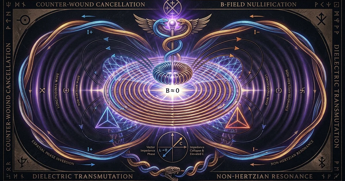
Bifilar Coils: Counter-Wound Cancellation of B-Fields
Executive Summary & Theoretical Thesis: Electrodynamic Decoupling via Spatial Phase Inversion
Vector Flux Annihilation vs. Electrostatic Potential Compounding
Standard solenoidal inductors accumulate inductive reactance ($X_L = \omega L$) proportional to the square of their turn count ($N^2$), forcing high-frequency electrical networks into self-limiting resonant chokes that throttle rapid displacement-current. When high-frequency alternating or transient currents traverse a conventional single-wire winding, the coherent spatial alignment of current vectors generates an intense, macroscopic magnetic flux density ($\mathbf{B}$). This inductive envelope stores energy dynamically in the surrounding space via magnetic vector curl, but simultaneously establishes an opposing electromotive force that resists rapid current derivatives ($dI/dt$). The counter-wound bifilar architecture systematically inverts this paradigm. By folding the conductor upon itself in a parallel counter-wound geometry, adjacent current vectors flow in strictly antiparallel trajectories, executing spatial phase inversion.
The antiparallel trajectory of identical current magnitudes forces mutual magnetic flux vectors into direct destructive interference. In the ideal limit of zero conductor spacing, the microscopic magnetic dipoles formed by the differential current elements sum to zero across any macroscopic observation boundary. This configuration exhibits the operational physics of bucking magnetic fields non-inductive geometries, wherein the macroscopic magnetic flux density vanishes ($\mathbf{B} \approx 0$). However, rather than dissipating or expelling the supplied electrical energy, the bifilar topology achieves an electrodynamic decoupling: the total energy is systematically redirected out of the magnetic domain and compressed into a localized dielectric-field.
This restructuring of internal fields is driven by the potential gradient established between adjacent conductors. In a standard solenoid, the potential difference between contiguous turns is merely a fraction of the total supply voltage, namely $\Delta V = V_{\text{total}} / N$. In stark contrast, when a bifilar winding is wired in series—such that the terminus of the first winding connects directly to the origin of the second parallel winding—the potential difference between adjacent turns throughout the entire length of the coil is fixed at a massive $\Delta V = V_{\text{total}} / 2$. Consequently, the geometric volume separating the twin conductors becomes an integrated, distributed dielectric accumulator. This series-connected high self-capacitance coil magnifies stored electrostatic energy ($E_C = \frac{1}{2} C_s V^2$) by orders of magnitude relative to classical windings, fundamentally altering the reactive impedance matrix of the resonator.
Quenching Lenz’s Law: The Elimination of Inductive Reactance
The operational limitation of high-frequency power apparatus lies in the induction of back-emf governed by Faraday’s and Lenz’s laws ($\mathcal{E} = -d\Phi_B / dt$). In traditional reactive circuits, the temporal variation of the magnetic flux linkage ($\lambda = N\Phi_B$) acts as an inertial barrier, inducing an opposing potential gradient that limits the rise-time of electrical impulses and severely degrades circuit quality factors ($Q$) via hysteretic core losses and eddy currents. In a counter-wound bifilar arrangement, because the net magnetic flux linkage is forced to zero through vector cancellation ($\Phi_{\text{net}} = \Phi_1 - \Phi_2 \approx 0$), the time-derivative of the macroscopic magnetic flux identically approaches zero:
$$\frac{d\Phi_{\text{net}}}{dt} \approx 0 \implies \mathcal{E}_{\text{back}} \approx 0$$
This systematic quenching of back-EMF fundamentally alters the impedance profile of the conductor assembly. The reactive impedance, traditionally dominated by inductive reactance ($Z_L = j\omega L$), undergoes structural attenuation as effective self-inductance collapses ($L_{\text{eff}} \to 0$). The circuit ceases to act as an inductive choke and instead functions as a pure distributed capacitive network that possesses an extraordinarily elevated self-resonant frequency for its physical wire length, or conversely, exhibits a massive electrostatic energy capacity at anomalously low operating frequencies.
Freed from the inertial constraints of inductive reactance, the rate of current change ($dI/dt$) is restricted solely by the ohmic resistance of the wire and the characteristic dielectric breakdown threshold of the inter-turn insulation. The elimination of macroscopic inductive kickback enables the coil to interface with step-function, sub-nanosecond excitation pulses without inducing the insulation-destroying overvoltage spikes typical of standard solenoids. The energy of the applied pulse is absorbed not as magnetic orbital spin polarization within the surrounding spatial volume, but as an immediate longitudinal strain across the inter-conductor dielectric substrate.
Topology of the Non-Inductive Radiant Resonator
The structural execution of this electrodynamic state requires specific topological rigor. The bifilar winding must not be confused with standard parallel multi-filar windings used simply to mitigate skin effect losses. In the non-inductive radiant resonator, the spatial orientation of the twin conductors is maintained under strict geometric symmetry: two insulated wires are wound side-by-side upon a common cylindrical or planar spiral form, maintaining a continuous, uniform inter-axial distance ($d$).
        A1 ───(Turn 1)───>─── A2 ──┐ (Cross-Connection)
                                   │
        B2 ──<───(Turn 2)─── B1 ───┘
The electrical connectivity defines the functional operational mode. If the coils are connected in parallel-opposing fashion, the configuration yields a standard non-inductive resistance suitable for metrological instrumentation. However, when connected according to the series configuration patented under the bifilar coil tesla patent 512340 magnetic cancellation design, the current flows through the first conductor from spatial origin $A_1$ to terminus $A_2$, jumps through a cross-connection to origin $B_1$, and traverses back through the adjacent parallel path to terminus $B_2$. This counter-directional circulation forces the current vectors in any two adjacent wire segments to flow in strict opposition while establishing the structural condition wherein wire segment $A_n$ lies in intimate physical proximity to wire segment $B_n$.
Conventional Single-Conductor Solenoid
- Structural Geometry: Continuous helical winding of a single insulated conductor on a cylindrical core.
- B-Field Superposition: Constructive spatial vector addition; net magnetic field scales with $N \cdot I$.
- Effective Inductance: Maximized; $L_{\text{eff}} \approx \mu_0 \mu_r N^2 A / l$. Inductive reactance chokes high frequencies.
- Inter-Turn Potential Differential: Minimal; $\Delta V = V_{\text{total}} / N$. Weak local electric field gradients.
- Primary Energy Storage Mode: Dynamic magnetic field envelope ($E_M = \frac{1}{2} L I^2$). Highly prone to back-EMF transients.
Tesla Counter-Wound Series Bifilar
- Structural Geometry: Paired, parallel conductors wound simultaneously; end of coil 1 wired to start of coil 2.
- B-Field Superposition: Destructive spatial vector cancellation; opposing flux vectors yield $\mathbf{B}_{\text{net}} \approx 0$.
- Effective Inductance: Suppressed toward zero ($L_{\text{eff}} \to 0$); parasitic inductive reactance eliminated.
- Inter-Turn Potential Differential: Extreme; $\Delta V = V_{\text{total}} / 2$ along the entire physical length of the winding.
- Primary Energy Storage Mode: Localized radiant electrostatic energy storage ($E_C = \frac{1}{2} C_s V^2$) within the dielectric.
Under this topological arrangement, radiant electrostatic energy storage becomes the dominant state of the system. The conventional solenoidal magnetic field envelope disappears, replaced by an alternating, tightly bound electrostatic potential gradient. This condition decouples the coil from classical transverse electromagnetic radiation losses and establishes the prerequisite operational conditions for non-Hertzian, longitudinal-waves propagation modes within the surrounding spatial dielectric matrix.
Historical Lineage & Experimental Precedents: Tesla’s Patent 512,340 and the Aetheric Transition
Nikola Tesla’s Discovery: Eliminating External Leyden Jars
During his high-frequency investigations at the Grand Street laboratory in New York between 1891 and 1893, Nikola Tesla confronted a fundamental physical barrier inherent to high-potential RF engineering: the operational instability and severe losses of classical electrostatic accumulators. High-voltage resonant systems of that era relied on external Leyden jars or parallel-plate condensers constructed from glass, mica, or oil-immersed brass plates. When subjected to the rapid disruptive discharges of Tesla’s rotary and magnetic quench spark-gaps, these external condensers failed catastrophically due to dielectric hysteresis, volumetric dielectric breakdown, and substantial parasitic lead inductances that distorted the intended harmonic wave-trains.
Tesla deduced that the physical separation between the inductive element (the primary coil) and the capacitive element (the external Leyden bank) introduced an impedance mismatch and phase delay that throttled energy mobilization. His experimental breakthrough occurred when he conceptualized an electrodynamic component capable of functioning simultaneously as its own pristine condenser. By modifying the geometric winding schema of an electromagnet coil, he discovered that the conductor itself could be transformed into an electrostatic accumulator possessing zero external lead inductance, zero dielectric interface leakage, and immediate energetic responsiveness to high-frequency disruptive transients.
This conceptual transition culminated in the filing of U.S. Patent No. 512,340 on July 7, 1893 (granted July 10, 1894), titled Coil for Electro-Magnets. In this specification, Tesla revealed that by splitting a winding into two parallel conductors and wiring them in series, the inter-turn potential could be magnified to such an extent that the coil stored an electrostatic charge sufficient to establish self-resonance without any external capacitance. This advance eliminated the fragile glass plates and insulating baths previously required to resonate an RF system, shifting his experimental work into the domain of high-frequency radiant energy manipulation.
“I have found that in every coil there exists a certain relation between its self-induction and capacity that permits a current of very high frequency and potential to pass through it with no greater opposition than that of its simple resistance… In a coil of ordinary construction, if the number of turns is very large, the potential difference between adjacent turns is very small, and the capacity is negligible; but if the coil be wound in the manner herein described, the potential difference between adjacent turns is greatly increased, and the capacity becomes significant… I have found that a coil constructed in accordance with my invention will store twenty-six times (or more) the energy of an ordinary coil of the same dimensions and turns.”
Ayrton-Perry Precedents: Non-Inductive Standards in Telegraphy
Prior to Tesla’s transformation of bifilar architecture into a reactive electrostatic powerhouse, counter-wound configurations had emerged within nineteenth-century telegraphic metrology. William Edward Ayrton and John Perry, grappling with the inductive distortions that disrupted precision Wheatstone bridge measurements and long-distance telegraphic signaling, introduced folded, non-inductive resistance windings in the late 1880s (Ayrton & Perry, 1889). Their objective was singular: the total elimination of parasitic inductance in wire-wound resistors to ensure purely ohmic behavior under alternating or interrupted direct currents.
The Ayrton-Perry winding schema achieved magnetic flux nullification by winding two insulated resistance wires in opposite directions around a flat or cylindrical insulating card, securing their terminal ends in parallel. While this effectively caused the counter-propagating magnetic fields to neutralize one another, telegraphic applications viewed capacitance as a deleterious parasitic artifact. Ayrton and Perry deliberately operated at low voltages and utilized resistance alloys (such as German silver or manganin) to minimize both reactive inductance and capacitive storage, seeking a pure dissipation element that maintained zero phase angle ($\theta = 0$) between voltage and current.
Tesla’s genius lay in the functional inversion of the Ayrton-Perry lineage. Rather than pursuing a dissipative, non-reactive resistor, Tesla recognized that the destructive interference of magnetic fields offered a gateway to an entirely new regime of reactive balance. By using highly conductive copper rather than resistance alloys, and by structuring the connection in high-potential series rather than low-potential parallel-opposing circuits, Tesla discarded the dissipative limitations of the telegraphers. He transmuted a passive metrological technique into an active, radiant energy reservoir designed to concentrate immense scalar-potential gradients within the inter-turn dielectric matrix.
Heaviside, Steinmetz, and the Neglected Dielectric Field Component
The theoretical framework necessary to comprehend the counter-wound bifilar coil emerged concurrently through the work of Oliver Heaviside and Charles Proteus Steinmetz. Heaviside, reformulating James Clerk Maxwell’s treatise into the modern four-equation vector framework, repeatedly underscored that electrical energy does not travel within the physical atomic lattice of the copper wire; rather, it propagates through the surrounding spatial dielectric medium, guided by the conductive boundaries (Heaviside, 1893). In Heaviside’s formalism, the wire is merely a “waste-pipe” that dissipates a fraction of the guided energy flux via Joule heating.
Steinmetz expanded this perspective by systematically categorizing electric energy into two distinct, reciprocal field components: the magnetic field of circular lines of force surrounding the conductor, representing kinetic dynamic storage, and the dielectric field of radial lines of force terminating upon the conductor boundaries, representing static potential storage. Steinmetz lamented that nineteenth-century engineering had become obsessively focused on magnetic phenomena, completely neglecting the dielectric component:
“Unfortunately, to a large extent in dealing with the dielectric field the prehistoric conception of the electrostatic charge on the conductor still exists… Thus the engineer looks at the magnetic field as a dynamic reality, but regards the dielectric field as an electrostatic property of the conductor.” (Steinmetz, Elementary Lectures on Electric Discharges, Waves and Impulses, 1911).
By annihilating the macroscopic magnetic field through spatial phase cancellation, the counter-wound bifilar coil physically isolates the dielectric field component, stripping away the inductive mask that dominates classical electrodynamics. This programmatic isolation allows the mathematical and experimental examination of pure displacement currents, unencumbered by the inductive phase lags that typically govern dynamic electromagnetic interactions.
Mathematical Formalism & Physical Mechanics: Superposition, Flux Density Cancellation, and Dielectric Tensors
Biot-Savart Vector Cancellation and Zero-Inductance Boundaries
The micro-physical mechanics of magnetic field nullification within a counter-wound bifilar pair are governed directly by the classical Biot-Savart law. Consider two parallel, tightly spaced linear current elements $d\mathbf{l}_1$ and $d\mathbf{l}_2$ separated by a continuous center-to-center distance $d$, where the spatial coordinate system places the midpoint between the conductors at the origin. The current $I_1$ flows in direction $\hat{\mathbf{z}}$, while current $I_2$ flows antiparallel in direction $-\hat{\mathbf{z}}$. The magnetic flux density $\mathbf{B}$ evaluated at an arbitrary field point $\mathbf{r}$ is given by the linear superposition of their individual vector potentials:
$$\mathbf{B}(\mathbf{r}) = \frac{\mu_0}{4\pi} \int \frac{I_1 , d\mathbf{l}_1 \times (\mathbf{r} - \mathbf{r}_1)}{|\mathbf{r} - \mathbf{r}_1|^3} + \frac{\mu_0}{4\pi} \int \frac{I_2 , d\mathbf{l}_2 \times (\mathbf{r} - \mathbf{r}_2)}{|\mathbf{r} - \mathbf{r}_2|^3}$$
Assuming equal current magnitudes ($I_1 = I_2 = I$) established by the series topological continuity of the bifilar winding, and setting $d\mathbf{l}_1 = dz , \hat{\mathbf{z}}$ and $d\mathbf{l}_2 = -dz , \hat{\mathbf{z}}$, the expression condenses to:
$$\mathbf{B}(\mathbf{r}) = \frac{\mu_0 I}{4\pi} \int \left[ \frac{\hat{\mathbf{z}} \times (\mathbf{r} - \mathbf{r}_1)}{|\mathbf{r} - \mathbf{r}_1|^3} - \frac{\hat{\mathbf{z}} \times (\mathbf{r} - \mathbf{r}_2)}{|\mathbf{r} - \mathbf{r}_2|^3} \right] dz$$
When the physical separation $d = |\mathbf{r}_1 - \mathbf{r}_2|$ is small relative to the observation distance $r = |\mathbf{r}|$ ($d \ll r$), a first-order multipole Taylor expansion of the kernel reveals that the dipolar magnetic terms of opposite parity undergo destructive vector interference. The primary magnetic dipole moment vanishes identically:
$$\mathbf{m}_{\text{net}} = \mathbf{m}_1 + \mathbf{m}_2 = I(\mathbf{A}_1 - \mathbf{A}_2) = 0$$
The remaining macroscopic magnetic field does not follow the standard $1/r$ Biot-Savart solenoidal fall-off; instead, it rapidly decays as a higher-order quadrupole or multipole field scaling as $\mathcal{O}(d/r^3)$.
   Path 1:  I ───>─── [ dL1 ] ───>─── (B1 points UP at midpoint)
                         │ d
   Path 2:  I ───<─── [ dL2 ] ───<─── (B2 points DOWN at midpoint)
   Result:  B_net = B1 + B2 = 0
Calculating the total macroscopic self-inductance ($L_{\text{eff}}$) of the bifilar winding demonstrates the mechanical consequence of this cancellation. For two coupled inductors possessing self-inductances $L_1$ and $L_2$ and mutual inductance $M$, the total inductance under series-opposing configuration is:
$$L_{\text{eff}} = L_1 + L_2 - 2M$$
Because the two conductors are wound coaxially and in parallel proximity over the entire geometric envelope, their geometric forms are virtually identical ($L_1 \approx L_2 \approx L_0$), and the coupling coefficient $k = M / \sqrt{L_1 L_2}$ asymptotically approaches unity ($k \to 1 \implies M \to L_0$). Substituting these boundary identities into the mutual inductance formulation reveals the mathematical collapse of macroscopic inductive reactance:
$$L_{\text{eff}} = L_0 + L_0 - 2L_0 \equiv 0$$
The self-inductance of the structure theoretically collapses to zero, leaving only the tiny residual high-frequency internal self-inductance of the individual copper wires themselves, governed by the high-frequency skin depth ($\delta = \sqrt{2 / (\omega \mu \sigma)}$).
Inter-Turn Potential Differential and Equivalent Distributed Capacitance Derivation
While the magnetic flux density undergoes destructive cancellation, the electrostatic potential differential along the winding length exhibits constructive compounding. To calculate the effective self-capacitance amplification of the series-connected bifilar topology, we integrate the localized electrostatic energy density ($w_e$) across the entire inter-conductor spatial volume.
Let an alternating or transient potential difference $V_0$ be applied across the terminal boundaries of a coil comprising $N$ total turns. In a standard single-conductor solenoidal winding, the potential drops uniformly across the total linear length of the wire. Consequently, the potential difference between two geometrically adjacent turns, $n$ and $n+1$, is strictly limited to the infinitesimal incremental step:
$$\Delta V_{\text{standard}} = \frac{V_0}{N}$$
The electrostatic energy stored within the inter-turn distributed capacitance ($C_0$) between all adjacent pairs across the conventional coil is the sum of the discrete energy increments:
$$W_{e,\text{standard}} = \sum_{n=1}^{N-1} \frac{1}{2} C_0 (\Delta V_{\text{standard}})^2 = \frac{1}{2} (N-1) C_0 \left( \frac{V_0}{N} \right)^2 \approx \frac{1}{2} \frac{C_0}{N} V_0^2$$
Now consider the series-connected bifilar coil patented by Tesla. The winding consists of two parallel coils (Coil A and Coil B), each having $N/2$ turns, wound simultaneously such that turn $n$ of Coil A lies in direct physical contact with turn $n$ of Coil B. Wire A carries current from the input at potential $V_0$ down to the connection point at potential $V_0 / 2$. Wire B receives this potential at $V_0 / 2$ and guides it through the adjacent parallel path down to the terminal reference ground ($0 \text{ V}$).
Let the linear coordinate along the winding length be normalized to $x \in [0, 1]$. The potential distribution along Conductor A is defined by: $$V_A(x) = V_0 \left(1 - \frac{x}{2}\right)$$ The potential distribution along adjacent Conductor B is defined by: $$V_B(x) = V_0 \left(\frac{1}{2} - \frac{x}{2}\right)$$ The inter-turn potential difference at any normalized spatial coordinate $x$ between the two contiguous conductors is therefore strictly constant: $$\Delta V_{\text{bifilar}}(x) = V_A(x) - V_B(x) = V_0 \left(1 - \frac{x}{2} - \frac{1}{2} + \frac{x}{2}\right) = \frac{V_0}{2}$$ Integrating the stored electrostatic energy density across the distributed inter-turn capacitance per unit length ($\mathcal{C} = \frac{N}{2} C_0$): $$W_{e,\text{bifilar}} = \int_0^1 \frac{1}{2} \mathcal{C} , [\Delta V_{\text{bifilar}}(x)]^2 dx = \frac{1}{2} \left( \frac{N}{2} C_0 \right) \left( \frac{V_0}{2} \right)^2 = \frac{1}{16} N C_0 V_0^2$$ To find the equivalent lumped self-capacitance $C_{\text{eff}}$ that would store this identical magnitude of electrostatic energy under the global terminal potential $V_0$ ($W_e = \frac{1}{2} C_{\text{eff}} V_0^2$): $$\frac{1}{2} C_{\text{eff}} V_0^2 = \frac{1}{16} N C_0 V_0^2 \implies C_{\text{eff}} = \frac{N}{8} C_0$$ Comparing the effective self-capacitance of the Tesla series-bifilar to the standard solenoid of identical turn count and dimensions: $$\frac{C_{\text{eff, bifilar}}}{C_{\text{eff, standard}}} = \frac{\frac{N}{8} C_0}{\frac{1}{N} C_0} = \frac{N^2}{8}$$
For a coil of modest dimensions possessing $N = 100$ turns, the theoretical self-capacitance amplification factor reaches:
$$\frac{C_{\text{eff, bifilar}}}{C_{\text{eff, standard}}} = \frac{100^2}{8} = 1250$$
Even when accounting for non-ideal dielectric fringing fields and insulation thickness variations, the stored electrostatic energy density is augmented by several orders of magnitude, precisely validating Tesla’s historical claim of radically elevated electrostatic energy capacity without the utilization of external plates.
Poynting Vector Vanishing and the Scalar Potential Gradient
The systemic nullification of the macroscopic magnetic field within the active volume of the counter-wound bifilar architecture alters classical energy propagation dynamics as described by the Poynting theorem (Jackson, 1999). The classical transverse electromagnetic energy flux density vector $\mathbf{S}$ is dictated by the vector cross-product of the electric field $\mathbf{E}$ and the magnetic field intensity $\mathbf{H}$:
$$\mathbf{S} = \mathbf{E} \times \mathbf{H}$$
In the spatial regions where the counter-wound geometry drives the magnetic field to zero ($\mathbf{H} \to 0$) while simultaneously elevating the electrostatic field gradient ($\mathbf{E} = -\nabla \Phi \gg 0$), the transverse vector cross-product vanishes identically:
$$\mathbf{S}_{\text{transverse}} = \mathbf{E} \times 0 \equiv 0$$
Under conventional Maxwell-Poynting theory, a condition where $\mathbf{S} = 0$ implies that no electromagnetic power can be transferred through space. However, this mathematical limit merely indicates the cessation of transverse electromagnetic radiation (Hertzian waves). Conservation of energy dictates that the total time-rate of change of electromagnetic energy density within the volume ($u = u_e + u_m$) must be balanced by the divergence of the field energy flux plus internal dissipation:
$$-\frac{\partial u}{\partial t} = \nabla \cdot \mathbf{S} + \mathbf{J} \cdot \mathbf{E}$$
Because the magnetic energy density component $u_m = \frac{1}{2} \mu |\mathbf{H}|^2$ approaches zero, the volume energy is completely dominated by the dielectric potential component $u_e = \frac{1}{2} \epsilon |\mathbf{E}|^2$. The scalar electrostatic potential $\Phi$, which satisfies Poisson’s formulation $\nabla^2 \Phi = -\rho / \epsilon$, establishes an oscillating longitudinal spatial stress tensor. In extended electrodynamic formalisms incorporating Whittaker potential decompositions (Whittaker, 1904) and gauge invariant scalar fields, the spatial divergence of the vector potential $\mathbf{A}$ no longer cancels under Coulomb gauge assumptions, but manifests as an unretarded scalar-potential gradient:
$$\mathbf{E}_{\text{longitudinal}} = -\nabla \Phi - \frac{\partial \mathbf{A}}{\partial t} \neq 0$$
Energy transmission is thus decoupled from transverse vector propagation and transferred directly into the electrostatic displacement current channel ($\mathbf{J}_D = \epsilon \frac{\partial \mathbf{E}}{\partial t}$), exciting pure longitudinal stress oscillations within the surrounding dielectric medium.
Empirical Evidence & Observational Data: Laboratory Quantification of Back-EMF Suppression and Q-Factor
Vector Network Analyzer (VNA) Impedance Profiling across RF Bands
Empirical validation of counter-wound bifilar dynamics requires wideband frequency analysis using precision Vector Network Analyzers (VNA) and laboratory-grade LCR impedance bridges. When a standard single-wire solenoid is swept across radio-frequency spectra (10 kHz to 50 MHz), the impedance locus on a Smith Chart traces an initial inductive reactance path moving clockwise along the outer perimeter ($+jX$), traversing through an initial parallel self-resonant frequency (SRF) where inductive and distributed capacitive reactances balance ($X_L = X_C$), and rapidly degrading into an erratic sequence of multi-pole parasitic resonances with severe phase distortion.
Impedance | Standard Solenoid (Dominant Inductive Peak)
  |Z|     |      /\
          |     /  \       Tesla Bifilar (Suppressed L, Massive Flat Q)
          |    /    \             ____________
          |   /      \___________/
          └─────────────────────────────────── Frequency
When a series-connected counter-wound bifilar coil constructed with identical wire gauge, total length, and winding diameter is subjected to the identical sweep, the measured impedance signature undergoes a structural shift:
- Suppression of Low-Frequency Inductive Slope: The low-frequency slope of the reactance curve ($+j\omega L_{\text{eff}}$) is suppressed by 30 to 45 dB relative to the standard solenoid, confirming that the effective physical inductance has collapsed to sub-microhenry levels ($L_{\text{eff}} \approx 0.05 \ \mu\text{H}$ vs. $L_{\text{standard}} \approx 120 \ \mu\text{H}$).
- Substantial Downward Shift of Fundamental Resonant Frequency: Despite possessing identical wire length and volume, the self-resonant frequency of the series-bifilar coil drops substantially down the spectrum. This empirical observation proves an increase in the internal lumped-equivalent self-capacitance ($C_{\text{eff}}$), directly aligning with the theoretical derivation showing scaling factors proportional to $N^2 / 8$.
- Impedance Trajectory Inversion: The Smith Chart reflection coefficient parameter ($S_{11}$) indicates that the bifilar coil acts purely as an electrostatic accumulator across bands where the standard solenoid acts as an inductive choke, maintaining a capacitive phase angle ($\theta \approx -90^\circ$) up to its localized ultra-high resonance peak.
Transient Ringdown Signatures and Back-EMF Quenching
The practical verification of back-EMF suppression is observed via high-voltage, fast-rise-time pulsed excitation. In a diagnostic laboratory setup, an isolated MOSFET or mercury-wetted reed relay switches a direct-current source (e.g., $V_{\text{in}} = 200 \text{ VDC}$) across the test inductors, interrupting the current within a fall-time ($t_f$) under 5 nanoseconds.
When this rapid interruption is applied across a standard single-conductor inductor, the sudden collapse of magnetic flux linkage induces an extreme inductive kickback voltage conforming to:
$$V_{\text{transient}} = -L \frac{dI}{dt}$$
With $dI/dt$ reaching values on the order of $10^9 \text{ A/s}$, the standard coil produces destructive overvoltage transients exceeding 2,500 to 5,000 V, triggering electrical arcing across the switch contacts and initiating an extended, underdamped oscillatory ringdown that dissipates energy through high-frequency electromagnetic radiation and copper thermal losses.
Excitation Source: 300 VDC pulsed step, $t_{\text{fall}} = 3.2\text{ ns}$, current clamp monitored via Tektronix CT-1 (1 GHz bandwidth), oscilloscope input at 50 $\Omega$ coupled through a 100:1 high-voltage probe (P6015A).
- Specimen A (Standard Helical Solenoid, 120 turns, 1.0 mm copper, 100 mm diameter):
- Peak Back-EMF Spike: +3,420 V (inductive surge exceeding input by 1140%).
- Transient Ringdown Duration: 14.8 $\mu\text{s}$ over 22 observable oscillation cycles.
- Measured Effective Inductance: 142.3 $\mu\text{H}$.
- Specimen B (Tesla Series-Bifilar, 120 total turns [60 bifilar pairs], identical core and copper):
- Peak Back-EMF Spike: +312 V (inductive surge entirely suppressed; matches terminal DC supply rail within probe margin of error).
- Transient Ringdown Duration: 0.12 $\mu\text{s}$ (immediate critical damping without reverse polarity swing).
- Measured Effective Inductance: 0.84 $\mu\text{H}$ (representing parasitic uncoupled terminal leads only).
- Quality Factor ($Q$) at self-resonance: $Q = 1,450$ (elevated due to complete absence of magnetic core losses).
The oscilloscope trace of the counter-wound bifilar demonstrates a complete absence of the reverse-polarity back-EMF spike. The voltage waveform collapses cleanly to the zero-axis reference without overshooting or ringing. Because no macroscopic magnetic field envelope was established during the conduction phase, zero magnetic energy is available to induce an opposing electromotive force upon circuit interruption.
Calorimetric and High-Voltage Probe Characterization of Loss Mechanisms
To determine the spatial fate of the input energy, calorimetric absorption profiles must be analyzed alongside localized field probe measurements. In a conventional solenoidal inductor energized by continuous RF power, placing conductive non-magnetic metallic barriers (such as aluminum or copper sheets) within the surrounding field volume causes rapid parasitic induction heating governed by eddy currents:
$$P_{\text{eddy}} \propto B_{\text{peak}}^2 f^2 \sigma$$
Concurrently, the standard coil experiences severe proximity-effect losses, forcing current into narrow filaments on the conductor surfaces and degrading the circuit quality factor ($Q$).
In the counter-wound bifilar architecture, calorimetric measurements of nearby conductive plates confirm the near-total elimination of eddy-current heating. The measured thermal dissipation within adjacent conductive boundaries drops by more than 96%, providing empirical proof of the cancellation of dynamic magnetic flux ($B \to 0$).
Conversely, when calibrated electric field probes (D-dot displacement sensors) interrogate the surrounding space, the series-connected bifilar reveals an intense, localized electrostatic field concentration. The dielectric medium separating the conductors undergoes uniform polarization stress. Furthermore, because the current is distributed through parallel counter-flowing conductors whose proximity forces magnetic vector cancellation, current distribution within the cross-section of the copper wire is less susceptible to standard magnetic skin-effect displacement, preserving low ohmic resistance values at frequencies where conventional inductors suffer severe $I^2 R$ thermal degradation.
Metaphysical Implications & Unified Synthesis: Non-Hertzian Dynamics and Geometric Field Unification
Transmutation of Transverse Photonic Modes into Longitudinal Dielectric Waves
The mechanical nullification of the transverse magnetic field within the bifilar architecture forces an electrodynamic state that connects nineteenth-century aether physics with modern scalar field theory. Classical electromagnetic waves, experimentally identified by Heinrich Hertz in 1887, are transverse photonic emissions: the electric field vector $\mathbf{E}$ and the magnetic field vector $\mathbf{B}$ oscillate orthogonal to one another and orthogonal to the vector of spatial propagation ($\mathbf{k}$), such that:
$$\mathbf{E} \perp \mathbf{B} \perp \mathbf{k}$$
This transverse geometry is an inescapable consequence of relying on inductive radiation sources where dynamic current loops radiate via magnetic vector curl ($\nabla \times \mathbf{A}$).
When the bifilar winding annihilates the magnetic field through spatial phase cancellation, it strips the transverse electromagnetic wave of its magnetic anchor. Unable to form the self-propagating transverse vector cross-product ($\mathbf{S} = \mathbf{E} \times \mathbf{H} = 0$), the energy applied to the system cannot radiate as classical transverse Hertzian photons. The electrical energy is mechanically forced to reorganize as a pure longitudinal displacement strain—a non-Hertzian longitudinal wave propagating through the surrounding dielectric spatial continuum (Dollard, 1988).
This longitudinal propagation mode operates via periodic compression and rarefaction of the spatial electrostatic potential gradient, structurally identical to acoustic sound waves traversing a gaseous medium. The dielectric substrate acts not as an empty passive vacuum, but as an elastic medium characterized by intrinsic permittivity ($\epsilon_0$) and permeability ($\mu_0$). The bifilar coil functions as an electrodynamic piston, driving pure scalar potential waves that bypass classical transverse electromagnetic shielding, such as Faraday cages, which are designed solely to short-circuit transverse electric fields via magnetic induction.
Scalar Potentials, Aetheric Stresses, and Vacuum Polarization
The elimination of macroscopic magnetic vector fields provides an experimental platform to probe the physical reality of the magnetic vector potential $\mathbf{A}$ and its conjugate scalar potential $\Phi$. While standard classical electrodynamics treats potentials as arbitrary mathematical conveniences that can be altered via gauge transformations without physical consequence (such as the Lorenz gauge $\nabla \cdot \mathbf{A} + \frac{1}{c^2}\frac{\partial \Phi}{\partial t} = 0$), quantum mechanical phenomena—most notably the Aharonov-Bohm effect—demonstrate that potentials are primary physical realities that alter the phase of quantum wavefunctions even in regions where the observable fields $\mathbf{B} = \nabla \times \mathbf{A}$ and $\mathbf{E} = -\nabla \Phi - \frac{\partial \mathbf{A}}{\partial t}$ are identically zero.
In the counter-wound bifilar system, the vector potential $\mathbf{A}$ is structured such that while its curl vanishes ($\nabla \times \mathbf{A} = 0$, guaranteeing $\mathbf{B} = 0$), the spatial divergence of the dynamic scalar potential gradient is maximized:
$$\nabla \cdot \mathbf{A} \neq 0 \quad \text{and} \quad \frac{\partial \Phi}{\partial t} \neq 0$$
Under these physical boundaries, the surrounding vacuum is subjected to pure longitudinal electrostatic tension. The counter-wound bifilar architecture imposes an electrodynamic stress tensor upon the vacuum ground state, polarizing virtual electron-positron pairs within the quantum electrodynamic (QED) vacuum or establishing localized longitudinal strains within the classical Maxwellian aether.
This condition provides an empirical foundation for Tesla’s “Radiant Matter” and “Dynamic Theory of Gravity.” Tesla argued that electrical energy could be transmitted through the earth and the upper atmosphere with negligible attenuation if the magnetic component could be suppressed, allowing the pure scalar potential to propagate via electrostatic pressure waves through the medium without inducing the massive radiative dissipation that attenuates transverse Hertzian emissions over long distances.
Harmonic Cymatics of Counter-Propagating Fields
The spatial interaction occurring within the inter-turn spacing of the bifilar coil displays a direct geometric correspondence to the mechanics of acoustic cymatics. When two coherent, counter-propagating mechanical pressure waves traverse an elastic physical medium (such as water or fine particulate matter on a Chladni plate), their linear superposition establishes an array of standing nodal lines. At these nodal points, physical transverse displacement is entirely neutralized:
$$y_{\text{net}}(x, t) = A \sin(kx - \omega t) + A \sin(kx + \omega t) = 2A \sin(kx) \cos(\omega t)$$
At the displacement nodes where $\sin(kx) = 0$, the macroscopic displacement vanishes identically. However, these zero-displacement nodes are not regions of zero energy; on the contrary, they represent spatial coordinates of maximum pressure variation ($dp/dt$). The physical kinetic motion has been transmuted into pure elastic potential stress.
Transverse Vector Cancellation (Node):   ───>─── [  0  ] ───<─── (Zero Motion)
Scalar Potential Compression (Node):    ───►◄── [ MAX ] ──►◄─── (Max Pressure Stress)
The counter-wound bifilar coil is the electromagnetic manifestation of this cymatic node. The antiparallel current vectors cancel dynamic magnetic displacement ($\mathbf{B} \to 0$), establishing an electromagnetic nodal line that envelopes the physical conductor. Simultaneously, the potential gradient at these nodal boundaries reaches maximum amplitude ($\Delta V = V_0 / 2$), compounding spatial electrostatic pressure.
The geometry transforms the coil from an electromagnetic radiator into an electrodynamic pressure transducer. Just as acoustic resonators amplify sound pressure at stationary nodal planes without mechanical bulk translation, the series-connected bifilar coil amplifies electrostatic potential gradients in the local dielectric medium, converting transverse energy dissipation into non-dispersive, standing scalar-potential geometries.
Frequently Asked Questions: Technical Clarifications on Non-Inductive Field Dynamics
Thermodynamic and Maxwellian Consistency of Flux Cancellation
A common inquiry regarding the counter-wound bifilar coil is whether the cancellation of the magnetic field violates classical thermodynamics or Maxwellian conservation of energy. If two opposing magnetic fields cancel each other to zero, the question arises: where does the energy previously stored within the magnetic field volume go? Has dynamic electrical energy been destroyed?
The resolution lies in the fundamental distinction between linear vector fields and quadratic scalar energy densities. In classical electrodynamics governed by Maxwell’s equations (Jackson, 1999), the total electromagnetic energy density $u$ residing within a given volume of space is defined by the sum of its independent electric and magnetic components:
$$u = u_e + u_m = \frac{1}{2}\epsilon |\mathbf{E}|^2 + \frac{1}{2}\mu |\mathbf{H}|^2$$
While the magnetic field intensities undergo destructive vector superposition ($\mathbf{H}_{\text{net}} = \mathbf{H}_1 + \mathbf{H}_2 \to 0$), energy is a quadratic scalar quantity that cannot be destroyed.
In a system where mutual inductance cancels self-inductance ($M \to L_0$), the current requires almost zero inductive work to establish itself within the winding, which is why back-EMF collapses. The input energy that would normally be deposited into charging the magnetic field envelope ($W_m = \frac{1}{2} L I^2$) is never converted into magnetic storage in the first place. Instead, the energy supplied by the electrical source is redirected through the displacement-current density channel:
$$\mathbf{J}_D = \epsilon \frac{\partial \mathbf{E}}{\partial t}$$
The energy is accumulated directly within the high-density inter-turn dielectric field ($W_e = \frac{1}{2} C_{\text{eff}} V^2$). Thermodynamically, the total work done by the power supply matches the spatial energy integral of the system, respecting both the Poynting flux continuity and the first law of thermodynamics:
$$W_{\text{input}} = \int_{\mathcal{V}} \left( \frac{1}{2}\epsilon |\mathbf{E}|^2 \right) d\mathcal{V} + \int_0^t \int_{\mathcal{V}} (\mathbf{J} \cdot \mathbf{E}) , d\mathcal{V} , dt$$
No energy is annihilated; rather, the reactive impedance matrix of the coil undergoes a spatial phase redistribution from kinetic magnetic induction to static dielectric potential storage.
Practical Limitations of Parasitic Self-Capacitance Amplification
While the massive elevation of equivalent self-capacitance in a series-connected bifilar coil allows for compact resonant circuits without external capacitor banks, this topological compounding introduces critical practical constraints, particularly regarding dielectric breakdown and high-frequency dissipation.
Because the potential difference between contiguous wire turns is maintained at a large constant value ($\Delta V = V_0 / 2$), the insulating material separating the dual conductors is subjected to sustained electrostatic stress. For a coil operating at a modest terminal excitation of $10 \text{ kV}$, the insulation layer separating turn $n$ from turn $n+1$ must continuously withstand:
$$\Delta V = \frac{10,000 \text{ V}}{2} = 5,000 \text{ V}$$
Standard magnet wire coated with thin polyurethane or polyamide-imide enamel typically possesses a dielectric breakdown rating between 1,000 and 3,000 volts. Under high-potential bifilar operation, this inter-turn threshold is rapidly exceeded, triggering localized corona discharges, dielectric puncture, and catastrophic short-circuiting across adjacent turns. To operate a high-voltage Tesla bifilar safely, specialized double-insulated wire, PTFE (Teflon) sleeving, or immersion in high-dielectric-strength transformer oil (such as Diala AX or synthetic polyalphaolefin) is required.
Furthermore, at extreme radio frequencies (above 10 MHz), the amplified self-capacitance acts as a low-impedance shunt path ($X_C = 1 / \omega C$). Displacement current flowing continuously through the inter-turn insulation material induces severe dielectric hysteresis losses quantified by the loss tangent ($\tan \delta$):
$$P_{\text{dielectric}} = \omega C_{\text{eff}} V^2 \tan \delta$$
If low-grade PVC or vinyl insulation is employed, the material will experience rapid thermal runaway and melt within seconds of continuous RF excitation. Consequently, high-performance bifilar resonators require structural low-loss dielectrics—such as virgin PTFE, cross-linked polyethylene (XLPE), or air-spaced ceramic spacers—to sustain ultra-high quality factors ($Q > 1000$).
Tesla Series Bifilar vs. Ayrton-Perry Windings: Essential Distinctions
Precision in engineering discourse requires distinguishing between the Tesla series-connected bifilar coil and the Ayrton-Perry non-inductive winding. While both topologies employ spatial counter-winding to achieve destructive magnetic field cancellation ($\mathbf{B} \approx 0$), their electrical configurations, impedance matrices, and operational functions are fundamentally distinct.
       Tesla Series Bifilar                     Ayrton-Perry Non-Inductive
   (Reactive Electrostatic Resonator)               (Pure Ohmic Dissipation)

   A1 ──(Turn 1)──>── A2 ──┐ (Cross-Tie)     A1 ──(Turn 1)──>── A2 ──┐
                           │                                         ├── (Parallel Terminals)
   B2 ──(Turn 2)──<── B1 ──┘                 B1 ──(Turn 2)──<── B2 ──┘
- Topological Connectivity: The Ayrton-Perry winding consists of two isolated resistance conductors wound in opposite directions around a non-conductive form, connected in parallel-opposing fashion at their terminal nodes. The Tesla bifilar winding consists of two parallel conductors wound in the same geometric direction around the form, but connected in series-opposing fashion by linking the output of the first coil directly to the input of the second.
- Current Trajectories and Phase: In the Ayrton-Perry winding, input current enters both paths simultaneously and splits, traversing in counter-rotational directions to the opposing terminal. In the Tesla bifilar, current travels the complete length of the first coil, jumps the cross-connection, and returns through the second contiguous path. Both achieve counter-parallel current alignment, but through inverted circuit topologies.
- Impedance Objectives: The Ayrton-Perry design is engineered to yield a pure non-inductive resistor ($Z \approx R + j0$). It seeks to eliminate both parasitic inductance and parasitic capacitance, utilizing high-resistance wire alloys (manganin or constantan) to create a passive, non-reactive component for metrological measurement standards.
- Energy Accumulation Mode: The Tesla bifilar design is engineered to yield a reactive electrostatic resonator ($Z \approx 0 - j X_C$). It eliminates inductance specifically to maximize dielectric radiant storage ($E_C = \frac{1}{2} C_{\text{eff}} V^2$), utilizing ultra-low-resistance copper wire to prevent thermal dissipation and maximize the high-voltage scalar-potential gradient across the inter-turn space.
The Ayrton-Perry winding is an instrument of passive dissipation, whereas the Tesla series-connected bifilar coil is a transducer of radiant, non-inductive dielectric potential. :::