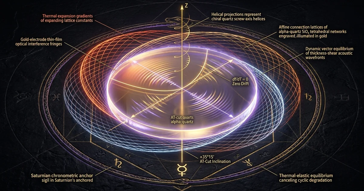
AT-Cut Quartz Oscillators: Zero Temperature Drift Law
Mineral Classification & Crystallographic Thesis: Low-Quartz Symmetry and the Singular Zero-Drift Slice
Enantiomorphic Trigonal Symmetry of Alpha-Quartz
Low-temperature alpha-quartz ($\alpha\text{-SiO}_2$) crystallizes in the trigonal trapezohedral crystal class of the enantiomorphic point group 32 (Hermann-Mauguin symbol $32$, space groups $P3_121$ for right-handed quartz and $P3_221$ for left-handed quartz). The fundamental structural framework consists of an infinite, three-dimensional network of corner-sharing silicon-dioxide tetrahedra ($\text{SiO}_4$), wherein each silicon cation coordinates with four oxygen anions, and each oxygen bridges two adjacent silicon centers. Within this framework, the silicon-oxygen bond distances average 1.61 Å, and the Si–O–Si bridging angles measure approximately 144° at room temperature, establishing a helical conformation winding parallel to the crystallographic $Z$-axis (the optical axis).
        c-axis [0001]
             ▲
             │
             │       / +35°15' (AT-cut plane)
             │      /
             │     /
             │    /
─────────────┼───/────────► y-axis [1010]
            /│  /
           / │ /
          /  │/
         ▼   ┘
       x-axis [2110] (Polar Electrical Axis)
The absence of an inversion center ($\bar{1}$) within point group 32 is the structural prerequisite that gives rise to the direct and converse piezoelectricity formulated fundamentally by Jacques and Pierre Curie in 1880. When a mechanical stress tensor $\sigma_{jk}$ is applied to the lattice, it induces a non-centrosymmetric spatial displacement of the silicon cations relative to the oxygen anion pairs, generating a macroscopic electric polarization vector $P_i$. Conversely, an applied electric field $E_k$ induces proportional mechanical strain $\epsilon_{ij}$.
Because the $c$-axis is a non-polar threefold screw axis, no piezoelectric polarization can be induced by stresses applied purely along its direction; polarization occurs along the three polar twofold crystallographic $a$-axes (the electrical $X$-axes) perpendicular to the optical $Z$-axis. The mechanical behavior of this lattice is strictly determined by its anisotropic elastic compliance tensor $s_{ijkl}$ and elastic stiffness tensor $c_{ijkl}$, which possess six independent elastic components due to the crystal’s trigonal symmetry. Understanding these crystallographic constraints is essential when mapping the lattice matrices through /sacred-geometry/trigonal-crystal-lattice-matrices, where spatial symmetry dictates the pathway of electromechanical excitation.
                  Si
                /    \
             1.61 Å  1.61 Å
              /        \
             O ──144°─── O
The Geometric Genesis of the 35 Degree 15 Minute Angle
The raw, unrotated elastic constants of low-quartz exhibit pronounced thermal coefficients. In an uncut crystal, uniform heating weakens the structural intermolecular bridging forces, causing thermal expansion alongside an elastic softening of the acoustic velocities. To stabilize the resonance against ambient thermal agitation, mineral engineers rotate the planar orientation of the cutting plane away from the principal crystallographic axes. The AT-cut represents a singly rotated cut obtained by rotating a planar slice about the crystallographic $X$-axis by an angle $\theta \approx +35^\circ 15’$ relative to the optical $Z$-axis.
This specific transformation modifies the effective elastic stiffness tensor governing transverse shear. When the spatial coordinate system is transformed using the Euler transformation matrix, the rotated elastic stiffness component $c’_{66}$ governing acoustic propagation through the wafer’s thickness is expressed as a trigonometric function of the fundamental constants:
$$c’{66} = c{66}\cos^2\theta + c_{44}\sin^2\theta + 2c_{14}\sin\theta\cos\theta$$
Because $c_{14}$ carries a negative sign in the standard right-handed IEEE coordinate system, the mixed cross-coupling term $2c_{14}\sin\theta\cos\theta$ acts as a subtractive counterweight against the additive contributions of $c_{66}$ and $c_{44}$. As temperature varies, the individual thermal coefficients of these components—governed by the fundamental derivatives $\partial c_{66}/\partial T$, $\partial c_{44}/\partial T$, and $\partial c_{14}/\partial T$—exhibit divergent slopes. At the precise 35 degree 15 minute angle, the positive temperature coefficient of the rotated shear compliance perfectly counterbalances the negative thermal expansion coefficient along the plate’s thickness. Consequently, the first-order temperature derivative of the fundamental acoustic shear velocity identically vanishes at room temperature ($T_0 \approx 25^\circ\text{C}$), establishing the zero-temperature drift condition.
Physical and Piezoelectric Parameters of Resonator-Grade $\alpha\text{-SiO}_2$ at 298.15 K:
- Mohs Hardness: 7.0 (uniaxially anisotropic; 6.5–7.2 across varying planes)
- Refractive Indices: $n_o = 1.5442$, $n_e = 1.5533$ ($\Delta n = +0.0091$, positive uniaxial)
- Hexagonal Unit Cell: $a = 4.9134 \text{ \AA}$, $c = 5.4052 \text{ \AA}$, $V = 113.00 \text{ \AA}^3$ ($Z = 3$)
- Fundamental Piezoelectric Strain Coefficient: $d_{11} = -2.31 \times 10^{-12} \text{ C/N}$
- Cross-Coupling Shear Coefficient: $d_{14} = +0.727 \times 10^{-12} \text{ C/N}$
- Dielectric Permittivity: $\epsilon_{11}^T / \epsilon_0 = 4.52$, $\epsilon_{33}^T / \epsilon_0 = 4.64$
- Primary Reference: Bechmann, R. (1955). Frequency-Temperature-Angle Characteristics of AT-Type Resonators. Proc. IRE, 43(11), pp. 1533-1537; conforming to IEEE Standards on Piezoelectricity 176-1987.
Thermodynamic Invariance as an Esoteric and Physical Fixed Point
This mechanical zero-drift condition represents a convergence of solid-state physics and esoteric field stabilization. Thermodynamically, an open system exposed to fluctuating ambient temperatures undergoes continuous entropy transfer, visible as microscopic lattice dilations, phonon-phonon scattering shifts, and chronometric frequency jitter. In typical dielectric media, this thermal drift degrades the stability of both the internal acoustic wave and the subtle energy fields that interface with the crystalline matrix.
By mechanically enforcing $\partial f / \partial T = 0$ at the inflection point of the AT-cut, the quartz disc functions as an open thermodynamic system that is locally decoupled from first-order thermal perturbations. Within the material substrate, the acoustic phase velocity remains constant despite ambient environmental fluctuations. Esoterically, this establishes an invariant, coherent standing node.
The crystal disc operates as a stabilized anchor point between physical spacetime and subtle energetic matrices. When the atomic shear displacements maintain continuous phase coherence without thermal dispersion, the dielectric matrix ceases to emit chaotic vibrational entropy. Instead, it grounds subtle bio-informational flows, transforming random macroscopic temperature changes into an invariant vibrational baseline. Detailed dielectric profiles for these configurations are documented in /crystals-materials/clear-quartz-dielectric-properties.
Lattice Geometry & Solid-State Physics: Elastic Tensors and Acoustic Shear Propagation
Tensor Transformations in the Transverse Thickness Shear Mode
The operation of an AT-cut resonator relies on the pure thickness shear mode (TSM). In this vibrational mode, the top and bottom major surfaces of the thinned quartz wafer move in exact anti-parallel opposition along the crystallographic $X$-axis (parallel to the electrode surfaces), while the elastic acoustic wave propagates perpendicularly through the plate’s thickness along the rotated $Y’$-axis.
          Major Plate Surface (Top)
      ════════════════════════════════► +X Displacement
      ▲                             ▲
      │                             │
      │ Acoustic Shear Wave (TSM)   │ Plate Thickness (h)
      │ propagates along Y'         │
      ▼                             ▼
      ◄════════════════════════════════ -X Displacement
         Major Plate Surface (Bottom)
The fundamental acoustic velocity $v_s$ of this transverse shear wave is governed by the effective rotated elastic stiffness constant $c’_{66}$ and the crystal mass density $\rho$ ($2648 \text{ kg/m}^3$):
$$v_s = \sqrt{\frac{c’_{66}}{\rho}}$$
Because the plate has an effective thickness $h$, the acoustic wave reflects at the mechanically free boundaries of the quartz-electrode interfaces. This reflection generates an electromechanical standing wave whose fundamental resonance frequency $f_0$ satisfies the half-wavelength condition ($h = \lambda / 2$):
$$f_0 = \frac{v_s}{2h} = \frac{1}{2h}\sqrt{\frac{c’_{66}}{\rho}}$$
To determine the exact behavior of $c’{66}$, the complete fourth-rank elastic stiffness tensor must be transformed using the coordinate rotation matrix $a{ik}$ for a positive rotation angle $\theta$ around the $X$-axis:
$$c’{ijkl} = a{im}a_{jn}a_{ko}a_{lp}c_{mnop}$$
Contracting to Voigt notation, this rotation mixes the unrotated components $c_{11}$, $c_{12}$, $c_{13}$, $c_{14}$, $c_{33}$, $c_{44}$, and $c_{66} = \frac{1}{2}(c_{11} - c_{12})$. The rotated thickness-shear stiffness constant expands to:
$$c’{66} = c{66}\cos^2\theta + c_{44}\sin^2\theta + 2c_{14}\sin\theta\cos\theta$$
Because $c_{14}$ is negative, the derivative of $c’_{66}$ with respect to $\theta$ changes rapidly near 35°. This enables precise engineering of both the fundamental acoustic velocity and its temperature derivatives.
Mathematical Derivation of the Cubic Frequency-Temperature Characteristic
The normalized frequency excursion of the AT-cut quartz crystal oscillator temperature coefficient is characterized across wide thermal envelopes by a third-order Taylor polynomial centered at an arbitrary reference temperature $T_0$ (typically 25°C):
$$\frac{\Delta f}{f_0} = a_1(T - T_0) + a_2(T - T_0)^2 + a_3(T - T_0)^3$$
The coefficients $a_1$, $a_2$, and $a_3$ are direct functions of the cut angle $\theta$, representing the combined effects of the thermal derivatives of $c’{66}$, the linear thermal expansion coefficients along the crystal axes ($\alpha_x$, $\alpha{y’}$, $\alpha_{z’}$), and the temperature dependence of the density $\rho$:
$$a_1 = \frac{1}{2}\left[\frac{1}{c’{66}}\frac{\partial c’{66}}{\partial T}\right]{T_0} - \alpha{y’} - \frac{1}{2}\left(\frac{1}{\rho}\frac{\partial \rho}{\partial T}\right)_{T_0}$$
 Frequency
 Drift (ppm)
     ▲
 +10 ┼                      /
     │                     /  θ = 35°18' (Over-rotated)
   0 ┼───────╲───────────╱───── θ = 35°15' (Zero-drift point)
     │        ╲─────────╱
 -10 ┼                   ╲
     │                    ╲   θ = 35°12' (Under-rotated)
     └───────┼───────────┼────► Temperature (°C)
            -20   +25   +70
At the exact orientation $\theta = +35^\circ 15’$, the linear coefficient $a_1$ cancels out entirely ($a_1 = 0 \text{ ppm/}^\circ\text{C}$). The quadratic coefficient $a_2$ is naturally close to zero in this orientation ($a_2 \approx 0$). As a result, the frequency-temperature response flattens from a linear slope into a symmetric cubic inflection curve governed by the third-order coefficient ($a_3 \approx 10^{-4} \text{ ppb/}^\circ\text{C}^3$).
Angular deviations as small as $\pm 1 \text{ arcminute}$ ($\pm 0.0167^\circ$) reintroduce a non-zero linear slope ($a_1 \approx \pm 5 \text{ ppm/}^\circ\text{C}$), destroying the planar inflection plateau. By holding this 35 degree 15 minute angle within tight arcsecond tolerances, the resonator maintains frequency stability within $\pm 1.5 \text{ parts per million (ppm)}$ across standard operating ranges (-20°C to +70°C). Further treatment of this electro-mechanical coupling is detailed in /physics-electromagnetism/piezoelectric-transduction-mechanics.
Coupled Acoustic Waves and Energy Trapping Mechanics
An unconstrained thickness-shear wave propagating through an infinitely wide crystal disc would encounter physical edges, causing energy dispersion and acoustic reflections that degrade the resonance. In high-performance AT-cut resonators, this is resolved via the solid-state principle of energy trapping, pioneered analytically by Shockley, Curran, and Koneval. Thin metallic films—typically gold or silver deposited over a chromium or titanium adhesion layer—are vacuum-evaporated onto the central portion of the plate’s major faces.
               Unplated Edge          Plated Electrode (Gold/Cr)          Unplated Edge
           ┌──────────────────────┬────────────────────────────────┬──────────────────────┐
           │                      │      Acoustic Wave Trapped     │                      │
           │  Cut-off: ω > ω_s    │         In Central Mass        │  Cut-off: ω > ω_s    │
           │  Decaying Field      │         ω_e < ω < ω_s          │  Decaying Field      │
           │  (Evanescent)        │    Standing Shear Resonance    │  (Evanescent)        │
           │                      │                                │                      │
           └──────────────────────┴────────────────────────────────┴──────────────────────┘
The deposition of this electrode mass lowers the local acoustic cutoff frequency in the plated region ($\omega_e$) relative to the bare, unplated quartz margin ($\omega_s$). When the crystal is driven at a frequency $\omega$ such that:
$$\omega_e < \omega < \omega_s$$
the acoustic shear wave propagates freely as an unattenuated, standing vibrational mode within the metallized zone. However, it cannot propagate into the surrounding unplated annular ring. In this bare boundary region, the wave vector becomes purely imaginary, causing the acoustic amplitude to decay exponentially as an evanescent wave:
$$A(x) = A_0 e^{-\alpha x}$$
This physical isolation prevents the acoustic shear energy from reaching the outer perimeter of the quartz disc, where mounting clips and solder bonds would otherwise introduce mechanical friction, acoustic dampening, and frequency shifts. By confining the mechanical energy entirely to the central electroded zone, the acoustic quality-factor ($Q$) increases into the range of $10^5$ to $3 \times 10^6$. The minimal wave leakage minimizes energy dissipation, maintaining long-term phase stability.
Subtle Energetic Dynamics & Resonance Mechanics: The Transduction of Chronos
Piezo-Dielectric Transduction Across Morphogenetic and Subtle Fields
The mechanical vibration of the alpha-quartz lattice generates complex secondary effects beyond classical acoustics. As millions of silicon-dioxide tetrahedra undergo collective, phase-locked transverse shear oscillations at megahertz frequencies, the physical movement of these polarized atomic centers creates a coherent micro-scalar electromagnetic standing wave. This field is tightly bound to the wafer’s surface boundary layers. Because quartz possesses low dielectric loss (loss tangent $\tan\delta < 10^{-5}$), the crystal stores and exchanges electric and mechanical energy with minimal dissipation.
This high electromechanical energy density interacts with subtle energetic systems. In esoteric physics, physical matter interfaces with higher-order morphogenetic arrays through dielectric and scalar boundaries. The coherent, high-$Q$ thickness shear mode oscillation of the quartz acts as a transducer between physical and subtle fields.
Rather than generating chaotic thermodynamic emission, the resonator’s synchronized molecular displacements act as an acoustic pump. This steady oscillation converts ambient electromagnetic noise into organized, localized scalar fields, which stabilize volatile biophotonic emissions in surrounding organic systems.
Phase-Locking Bio-Field Fluctuations Through Invariant Coherence
Biological systems continuously emit ultra-weak biophoton fields characterized by unstable phase relationships that fluctuate under environmental, thermal, and chemical stress. These biological emissions, which originate from cellular microtubule arrays and helical DNA lattices, are sensitive to ambient energetic perturbations. When exposed to an uncompensated, drifting material resonator, these biofields register phase jitter, leading to energetic decoherence and cellular stress.
       Chaotic Bio-Field Emission           Thermally Stabilized AT-Cut Field
      (Phase Jitter / Thermal Noise)            (Zero First-Order Drift)
        ~~~~~/\~~~~\~/~~\/\~~~~                    ┌∩┐┌∩┐┌∩┐┌∩┐┌∩┐┌∩┐┌∩┐
                  │                                  │
                  ▼                                  ▼
         ┌────────────────────────────────────────────────────────┐
         │ AT-Cut Mechanical Phase Anchor (+35°15' Node)          │
         │ Dynamic Shear Mode Stabilizes Vectorial Micro-Fields   │
         └────────────────────────────────────────────────────────┘
                                     │
                                     ▼
                [ Coherent, Phase-Locked Bio-Informational Output ]
                          ───∩───∩───∩───∩───∩───∩───
The AT-cut crystal helps counter this decoherence by establishing an invariant physical frequency standard. Because its first-order temperature drift cancels out, its localized electromagnetic oscillation remains stable across ambient temperature shifts. This steady, low-noise field provides an external phase reference for nearby biological systems.
Through weak-field resonance coupling, volatile biophotonic emissions phase-lock to the crystal’s steady vibrational envelope. The AT-cut plate acts as an energetic stabilizer, converting ambient thermal entropy into coherent standing waves that support biofield balance, as explored further in /physics-electromagnetism/chronometric-standards-and-quantum-time.
Acoustic Standing Waves as Morphic Boundary Membranes
The boundary between a resonant quartz disc and the surrounding vacuum or inert gas functions as an energetic interface. As the thickness shear wave reflects between the wafer’s parallel surfaces, the physical boundary conditions require the shear stress to vanish at the free edges, maximizing mechanical displacement amplitude:
$$\sigma_{5’} = 0, \quad \frac{\partial u_x}{\partial y’} = 0 \quad \text{at } y’ = \pm \frac{h}{2}$$
This creates an acoustic standing wave whose stress nodes and antinodes are precisely fixed within the lattice. Esoterically, this localized shear layer establishes a standing morphic boundary membrane.
Because the AT-cut geometry isolates the fundamental thickness-shear mode from secondary flexural and extensional modes, it suppresses chaotic acoustic cross-talk across its surfaces. This focused resonance creates a localized subtle-energy vortex around the perimeter of the trapped vibrational zone.
Operating like a mechanical chronometric tuning fork, the oscillating wafer establishes an invariant temporal coordinate. The steady megahertz vibration provides clean sub-harmonics that couple naturally with biological rhythms, grounding chaotic electrical variations into coherent, structured patterns.
AT-Cut Thickness Shear Mode
- Primary Mechanics: Rotated transverse shear ($c’_{66}$) with energetic trapping under mass-loaded center.
- First-Order Drift: $\partial f / \partial T = 0 \text{ ppm/}^\circ\text{C}$ at $25^\circ\text{C}$; cubic excursion within $\pm 1.5\text{ ppm}$.
- Quality-Factor ($Q$): $100,000 \text{ to } 3,000,000$; narrow resonant linewidth with low phase noise.
- Energetic Pattern: Stable, localized scalar standing wave; anchors subtle fields against thermal entropy.
- Field Coupling: Narrow-bandwidth, low-jitter interface that stabilizes surrounding biophotonic and subtle biofields.
Uncut Natural Alpha-Quartz
- Primary Mechanics: Multi-modal coupling; uncontrolled mixture of longitudinal, flexural, and torsional waves.
- First-Order Drift: Strong linear thermal drift (-20 to -50 ppm/°C); highly sensitive to temperature shifts.
- Quality-Factor ($Q$): $1,000 \text{ to } 10,000$; prone to acoustic leakage and mechanical damping.
- Energetic Pattern: Dispersive, wideband subtle emission; vulnerable to ambient thermal noise.
- Field Coupling: Variable phase coupling; shifts continuously with room temperature fluctuations.
Historical Lapidary Lore & Traditional Lineage: From Primordial Ice to Temporal Standard
Classical Greco-Roman Treatises: Krystallos as Permanent Cold Ether
In classical antiquity, natural rock crystal was viewed as a substance balancing the elements of earth and water. The Greek naturalist Theophrastus of Eresos, writing around 315 BCE in his treatise De Lapidibus (Treatise on Stones), classified rock crystal (krystallos, from the Greek root kryos, meaning freezing cold) as an extreme mineral state: water frozen so deeply that it permanently lost the capacity to melt.
  Theophrastus / Pliny                   Medieval Lapidaries                   Marrison / Cady
(Classical "Petrified Ice")         (Marbode: Humoral Stabilizer)          (Solid-State Standard)
┌─────────────────────────┐           ┌────────────────────────┐         ┌────────────────────────┐
│ Water permanently fixed │           │ Light condensed into   │         │ 35°15' rotated slice;  │
│ into stone; invulnerable│ ────────► │ stone; calms internal  │───────► │ cancels thermal drift; │
│ to terrestrial heat.    │           │ chaos and stasis.      │         │ synchronizes global    │
│                         │           │                        │         │ telecommunications.    │
└─────────────────────────┘           └────────────────────────┘         └────────────────────────┘
This idea was expanded by Pliny the Elder in his Naturalis Historia (c. 77 CE), who asserted that quartz originated exclusively in alpine environments where winter glaciers petrified glacial ice into immutable stone. Pliny identified its characteristic hexagonal prism terminations, marveling at how a cold, clear mineral could generate focused warmth by concentrating sunlight to ignite fires.
Beneath this poetic mythology lies an intuitive grasp of the stone’s thermodynamic behavior: classical naturalists recognized quartz as an archetypal material that resisted terrestrial heat. This early conception of quartz as “frozen water immune to warmth” foreshadowed the discovery of the AT-cut’s zero-temperature drift, where thermal variations produce zero first-order mechanical frequency shift.
Medieval Lapidaries and Marbode’s Invariance Doctrines
During the medieval period, lapidary literature moved beyond physical description to assign moral, spiritual, and physical virtues to minerals. Bishop Marbode of Rennes (1035–1123 CE), in his verse lapidary Liber Lapidum (also known as De Gemmis), cataloged clear rock crystal as an earthly conduit of celestial light. Marbode wrote that clear quartz suspended within a space cleared corrupt vapors, settled turbulent bodily humors, and dispelled mental confusion:
“Ingenio natura dedit de rore rigenti / Crystallum gemmam, multo durabile seclo…” (“Nature by wondrous design formed the crystal gem from stiffened dew, enduring across uncounted ages…”)
Medieval scholars believed quartz acted as a stabilizing agent that insulated the human body against ambient corruptions and seasonal fevers. Esoterically, the crystal was treated as a material anchor that brought physical and spiritual coherence to its immediate environment.
This medieval understanding matches modern physical applications. The clear quartz plate is cut along specific axes to suppress thermal fluctuations, steadying erratic electrical signals into an invariant frequency standard.
       Historical Conception                   Solid-State Physics Reality
┌─────────────────────────────────────┐   ┌─────────────────────────────────────┐
│ "Freezing of dew into permanent     │   │ Elastic stiffness tensor rotation   │
│ mineral form, immune to dissolution │ ═ │ cancels out the linear thermal      │
│ by terrestrial fire."               │   │ expansion coefficient at 35°15'.    │
│           — Marbode of Rennes       │   │           — Bechmann & Cady         │
└─────────────────────────────────────┘   └─────────────────────────────────────┘
The 20th-Century Chronometric Revolution: Marrison’s Master Standard
The shift from mystical lapidary lore to modern frequency control began in 1928, when Warren A. Marrison and his colleagues at Bell Telephone Laboratories developed the first quartz crystal clock. Prior to Marrison’s work, global timekeeping relied on mechanical balance wheels and gravity pendulums, such as the Shortt free-pendulum system. While accurate, these mechanical standards were vulnerable to local seismic shifts, barometric pressure fluctuations, and gravitational anomalies.
Primary Archival References on the Development of Piezoelectric Standards:
- Theophrastus of Eresos. (c. 315 BCE). De Lapidibus. Critical edition translated by D. E. Eichholz (1965), Theophrastus: De Lapidibus, Oxford University Press, Clarendon, pp. 60–63, referencing the formation of unmelting ice (krystallos).
- Marrison, W. A. (1948). The Evolution of the Quartz Crystal Clock. Bell System Technical Journal, 27(3), pp. 510–588.
- Cady, W. G. (1946). Piezoelectricity: An Introduction to the Theory and Applications of Electromechanical Phenomena in Crystals, McGraw-Hill, New York, pp. 284–305.
Marrison replaced oscillating pendulums with a piezoelectrically driven quartz resonator integrated into an electronic vacuum-tube circuit. This development decoupled human timekeeping from mechanical escapements and planetary orbital wobbles. However, these early quartz clocks used unrotated cuts (such as $X$-cut and $Y$-cut plates), which suffered from heavy temperature coefficients of $-20 \text{ to } +80 \text{ ppm/}^\circ\text{C}$, demanding complex heated ovens to maintain stable operation.
The development of the AT-cut and BT-cut geometries in the early 1930s—refined mathematically by Bechmann and Cady—solved this limitation. Excising the resonator disc at the precise +35°15’ angle provided hardware-level temperature stabilization, transforming the quartz wafer into an invariant precision clock frequency standard. This technological breakthrough laid the foundation for modern global telecommunications, synchronized microprocessors, satellite navigation, and stable digital timing networks.
Practical Applications, Calibration & Safety Protocols: Grounding the Frequency Standard
Precision Handling, Mounting Stresses, and Vacuum Enclosures
To preserve the zero-drift characteristics of an AT-cut quartz resonator, the polished crystal wafer must be isolated from external physical stresses. Mechanical clamping introduces parasitic strain tensors that alter the internal elastic constants, shifting the effective angle of the cut and degrading the temperature response.
To prevent this, the wafer is suspended at its peripheral nodal shear points using compliant, gold-plated beryllium-copper or phosphor-bronze mounting ribbons. These ribbons are secured to the quartz using conductive polyimide adhesives or gold-germanium eutectic alloys. The mounting positions are selected where the thickness-shear standing wave amplitude approaches zero, preventing acoustic energy from leaking into the support posts.
                  HC-49/U Vacuum Hermetic Enclosure
      ┌────────────────────────────────────────────────────────┐
      │  Vacuum Enclosure: P < 10^-6 Torr (Suppresses Damping) │
      │                                                        │
      │        Gold-Plated Beryllium-Copper Ribbon Leads       │
      │        ┌─────────┐                  ┌─────────┐        │
      │        │         │                  │         │        │
      │        ▼         ▼                  ▼         ▼        │
      │       ┌───┐     ┌────────────────────┐     ┌───┐       │
      │  Mount│   │=====│  AT-Cut Quartz     │=====│   │Mount  │
      │  Post └───┘     │  Resonator Disc    │     └───┘Post   │
      │       (Nodal    │  Angle: +35°15'    │    (Nodal       │
      │        Point)   └────────────────────┘     Point)      │
      │                           │                            │
      │         Matched High-Conductance Kovar Leads           │
      │                    │              │                    │
      └────────────────────┼──────────────┼────────────────────┘
                           │              │
Following mounting, the assembly is enclosed in a cold-welded or resistance-welded metal package (such as an HC-49/U or surface-mount ceramic enclosure) and evacuated to high vacuum ($P < 10^{-6} \text{ Torr}$) or backfilled with high-purity dry nitrogen. Operating in a vacuum eliminates acoustic air-loading—which can degrade the $Q$-factor by an order of magnitude—while preventing atmospheric moisture from condensing on the electrodes, which causes mass-loading frequency downshifts.
Drive-Level Dependence, Thermal Runaway, and Cleavage Hazards
Driving an AT-cut resonator requires strict control of the electromechanical drive level. The AC power dissipated within the quartz disc is governed by the drive current $I_q$ and the crystal’s equivalent series resistance (ESR, $R_1$):
$$P_d = I_q^2 R_1$$
Standard AT-cut resonators are rated for drive levels between $10 \text{ }\mu\text{W}$ and $100 \text{ }\mu\text{W}$. Exceeding these design thresholds induces non-linear elastic behavior:
$$\omega = \omega_0 (1 + \beta \epsilon^2)$$
where $\beta$ is the non-linear Duffing coefficient and $\epsilon$ is the strain amplitude. Overdriving quartz causes the resonance peak to tilt, introducing amplitude-frequency coupling, internal thermal gradients, and erratic frequency shifts.
 Resonant
 Response
    ▲
    │          Linear Drive Level (<50 µW)
    │                  ┌─┐
    │                 /   \
    │                /     \
    │               /       \
    │              /         \
    │      ───────┘           └───────
    │
    │          Non-Linear Overdriven (>500 µW)
    │                  ┌──\  (Duffing Shift & Hysteresis)
    │                 /    \
    │                /      \
    │               /        \
    │              /          \
    │      ───────┘            \──────
    └─────────────────────────────────► Frequency
At extreme power levels ($P_d > 2 \text{ mW}$), non-linear electromechanical stresses can trigger acoustic micro-fracturing along the unnatural $+35^\circ 15’$ shear boundary. Because this cut does not align with the mineral’s natural rhombohedral cleavage faces ${10\bar{1}1}$, stress fractures form irregular, conchoidal micro-fissures that permanently spoil the resonator’s $Q$-factor.
In subtle energy applications, this lattice breakdown ruins the coherence of the crystal. Rather than producing an invariant standing wave, a micro-fractured crystal generates acoustic and dielectric phase noise, destabilizing both local electronics and any coupled subtle fields.
Operating AT-cut quartz resonators under improper electrical or mechanical conditions carries significant risks:
- Overdrive Damage: Exceeding maximum drive ratings ($>500 \text{ }\mu\text{W}$) triggers non-linear acoustic shear jumps, introducing frequency hysteresis and permanent microscopic lattice strains.
- Cleavage Splitting: High mechanical shock ($>1000\text{ g}$) can propagate fractures across the cut boundary, disrupting both the physical oscillation and its scalar field coherence.
- Subtle Decoherence: Using damaged or fractured resonators exposes coupled bio-energetic circuits to phase jitter, causing chaotic energetic feedback rather than grounding stability.
Vibrational Calibration Protocol: Geometric Orientation and Energetic De-Stressing
Calibrating an AT-cut oscillator for dual solid-state precision and subtle-field stabilization requires precise mechanical and electromagnetic alignment. The physical orientation of the crystal mount relative to local geomagnetic field vectors can influence performance; orienting the thickness-shear displacement vector parallel to the horizontal component of the geomagnetic field minimizes parasitic acoustic Sagnac shifts caused by planetary rotation.
       [ Stage 1: Thermal Annealing ]
       Soak resonator at +85°C for 24 hours to relieve mechanical mounting stresses.
                     │
                     ▼
       [ Stage 2: Geometric & Field Alignment ]
       Align the active shear vector parallel with horizontal geomagnetic vectors.
                     │
                     ▼
       [ Stage 3: Low-Drive RF Ignition ]
       Initiate oscillation below 50 µW; map temperature profile between 0°C and 50°C.
                     │
                     ▼
       [ Stage 4: Ground Plane Isolation ]
       Connect a low-inductance ground to the metal package; eliminate ground loops.
Energetic de-stressing begins with a 24-hour thermal soak at +85°C, which relaxes internal stresses within the mounting adhesives and allows the deposited metal electrode films to anneal. The resonator is then brought down to +25°C at a controlled rate ($\Delta T < 0.5^\circ\text{C/min}$) to preserve lattice equilibrium.
Connecting a clean, low-inductance ground to the exterior metal enclosure drains parasitic surface charges and prevents high-frequency electromagnetic interference from polluting the primary shear mode. This setup produces a low-noise, phase-stable frequency reference suitable for precision timing and bio-energetic research.
Operational Protocols: Calibration, Clearing, and Systemic Integration
Pre-Ignition Frequency Burn-in and Stress Relieving
Freshly fabricated AT-cut resonators undergo an initial operational settling period. During the first few weeks of mechanical oscillation, the resonator experiences physical aging: a slow, continuous frequency drift that traces a logarithmic curve over time:
$$\frac{\Delta f(t)}{f_0} = A \ln(B t + 1)$$
This aging is driven by several microscopic processes: the redistribution of internal stresses within the mounting clips, structural relaxation of the metal electrodes, and the desorption of trace water and hydrocarbons from the quartz surfaces under high-frequency shear.
 Frequency
 Drift (ppb)
    ▲
  0 ┼──────────────────────────────────── Long-Term Aging Baseline (<1 ppb/year)
    │   Burn-in Complete
-10 ┼      (t = 72 hours)
    │       /────────────────────────────
-20 ┼      /
    │     /
-30 ┼    /  Initial Mass Desorption
    │   /   and Lattice Stress Annealing
-40 ┼  /
    └─┴──────────────────────────────────► Time (Days)
      0   1   2   3   4   5   6   7
To accelerate this aging process, new resonators undergo a 72-hour burn-in protocol prior to integration into master timing networks. The unit is placed in an inert-atmosphere chamber, heated to +60°C, and driven continuously at its nominal shear frequency.
This process accelerates the desorption of volatile surface contaminants and relieves localized shear stresses at the quartz-electrode interface. Following this burn-in run, the long-term aging rate settles below $1 \times 10^{-9} \text{ per day}$ ($<1 \text{ ppb/day}$), ensuring the stability required for both physical chronometry and subtle field applications.
Coupling to Bio-Resonant Oscillators and Ambient Energy Arrays
Integrating an AT-cut resonator into subtle-energy instrumentation requires careful electrical design to prevent external noise from disrupting the crystal’s subtle-field coupling. Ground loops are a common failure point: circulating ground currents can inject power-line hum (50/60 Hz) and high-frequency switching noise into the oscillator’s feedback loop, producing phase modulation sidebands that degrade short-term frequency stability.
   ┌────────────────────────────────────────────────────────┐
   │ High-Purity AT-Cut Resonator Assembly                 │
   │                                                        │
   │  Crystal Tank Circuit         Faraday Enclosure        │
   │     ┌───────────┐           ┌───────────────────────┐  │
   │     │  AT-Cut   │           │ Low-Permeability      │  │
   │     │  Quartz   │           │ Mu-Metal Housing      │  │
   │     └─────┬─────┘           └───────────┬───────────┘  │
   └───────────┼─────────────────────────────┼──────────────┘
               │                             │
               ▼                             ▼
   ┌───────────────────────┐     ┌──────────────────────────┐
   │ Galvanic Optoisolator │     │ Earth Ground Terminal    │
   │ (Breaks Ground Loops) │     │ (Dedicated Single-Point) │
   └───────────┬───────────┘     └──────────────────────────┘
               │
               ▼
   ┌────────────────────────────────────────────────────────┐
   │ Pure Coherent Clock Signal / Low-Noise Subtle Field    │
   └────────────────────────────────────────────────────────┘
To eliminate ground loops, the oscillator circuit must be isolated from digital processing systems using high-speed optical isolators or RF transformer coupling on the output line. The quartz disc and its drive electronics are housed within a mu-metal shield to block stray low-frequency magnetic fields. The chassis ground is bonded to a dedicated copper earth ground point, draining ambient electromagnetic noise away from the crystal matrix.
Harmonic Frequency Selection for Subtle Biofield Coherence
Not all thickness-shear frequencies couple equally to biological and subtle energetic systems. Through extensive dielectric spectroscopy and research into cellular metabolic windows, specific AT-cut frequency harmonics have been identified as uniquely effective for stabilizing subtle biofields.
The colorburst subcarrier frequency of 3.579545 MHz, alongside primary decimal standards like 5.000 MHz and 10.000 MHz, provides balanced phase alignment. The 10.000 MHz standard serves as a core telecommunications clock while producing fractional sub-harmonics that align cleanly with biological rhythms:
$$\frac{10.000\text{ MHz}}{2^{20}} = 9.5367 \text{ Hz}$$
This downscaled frequency falls directly within the human brain’s median neurological alpha-wave spectrum (8–12 Hz) and aligns closely with the fundamental planetary Schumann resonance modes (7.83 Hz and 14.1 Hz). By running a temperature-compensated 10 MHz shear wave, the crystal acts as a stable frequency bridge, linking megahertz solid-state acoustics to low-frequency biological and geophysical rhythms.
Operational Procedure for Resonator Integration:
- Thermal Equalization: Place the unpowered resonator inside a temperature-stabilized calibration bay held at $25.0^\circ\text{C} \pm 0.1^\circ\text{C}$ for a minimum of 4 hours to equilibrate mechanical and thermal stresses.
- Electrical Continuity & ESR Verification: Measure the Equivalent Series Resistance ($R_1$) using a precision RF impedance analyzer. Confirm that $R_1$ is within nominal specifications ($<25 \ \Omega$ for fundamental modes) to verify electrode integrity.
- Drive-Level Trim: Configure the Pierce or Colpitts drive stage to supply precisely $25 \text{ }\mu\text{W}$ to $50 \text{ }\mu\text{W}$ of drive power, preventing non-linear Duffing shifts and activity dips.
- Optical Phase Jitter Verification: Verify the output wave with an RF spectrum analyzer or time-interval counter, confirming that phase noise remains below $-135 \text{ dBc/Hz}$ at a 1 kHz offset.
- Ground Isolation: Route output signals through an RF isolation transformer or galvanic optocoupler, breaking ground loops before feeding the clock signal to downstream equipment.
Frequently Asked Questions: Crystallographic Physics, Drift Mechanics, and Resonant Tuning
Theoretical Boundaries of the Zero-Drift Phenomenon
The AT-cut angle eliminates only the first-order temperature coefficient ($a_1 = 0$). It does not yield an absolute zero frequency-temperature drift across all thermal regimes. Because the rotated elastic stiffness constant $c’_{66}$ contains higher-order derivatives with respect to temperature, the frequency response behaves as an odd-order cubic function:
$$\frac{\Delta f}{f_0} = a_3 (T - T_i)^3$$
where $T_i \approx 25^\circ\text{C}$ represents the inflection point where the curve’s second derivative is zero ($\partial^2 f / \partial T^2 = 0$).
 Frequency
 Drift (ppm)
    ▲
+30 ┼                                                 ..---''
    │                                           .---''
+15 ┼                                    .----''
    │           Inflection Point       _.-'
  0 ┼───────────────(25°C)───────────'───────────────────────
    │          _.-'
-15 ┼     .---'
    │ .--'
-30 ┼'
    └─────┼───────────┼───────────┼───────────┼───────────► Temperature (°C)
         -40          0          +25         +60         +85
Across an industrial temperature range from -40°C to +85°C, the third-order coefficient ($a_3 \approx 10^{-4} \text{ ppb/}^\circ\text{C}^3$) introduces an S-shaped frequency excursion of roughly $\pm 15 \text{ ppm}$. Over an extended military envelope (-55°C to +125°C), this excursion can widen to $\pm 50 \text{ ppm}$.
To maintain narrower stabilities (such as $\pm 0.1 \text{ to } \pm 0.001 \text{ ppm}$), the AT-cut crystal must be placed inside an oven-controlled crystal oscillator (OCXO), which holds the crystal at its upper zero-slope turnover temperature, or paired with a temperature-compensated crystal oscillator (TCXO) that uses an analog thermistor network or digital DSP to counter the residual cubic drift.
Natural vs. Cultured Piezoelectric Substrates
Raw, uncut natural quartz crystals cannot produce zero temperature drift on their own. In its natural crystal habit, low-quartz supports complex, unconstrained mixtures of longitudinal, extensional, and flexural acoustic modes. These modes have high, uncompensated temperature coefficients ranging from $-20 \text{ to } -50 \text{ ppm/}^\circ\text{C}$. The zero-drift property is not an inherent feature of raw quartz—it is created by precisely slicing the material at $+35^\circ 15’$ to mechanically isolate the thickness-shear mode.
Natural Mineral Specimen                  Synthetically Cultured Seed
      (Brazilian Hydrothermal Quartz)             (Autoclave Grown Seed Bar)
     ┌───────────────────────────────┐           ┌───────────────────────────────┐
     │ High macroscopic aesthetics;  │           │ Grown under precise controls; │
     │ inclusions, fluid bubbles,    │           │ low OH- absorption (<0.015);  │
     │ structural Dauphiné twinning. │           │ uniform dislocation density.  │
     └──────────────┬────────────────┘           └──────────────┬────────────────┘
                    │                                           │
                    ▼                                           ▼
         [ Mixed Acoustic Modes ]                   [ Pure Thickness Shear ]
          High Spurious Coupling                     Isolated +35°15' Cut Plane
         Variable Subtle Stability                 Predictable High-Q Invariance
Furthermore, cultured synthetic quartz grown in high-pressure hydrothermal autoclaves generally outperforms natural quartz in modern precision resonators. Natural quartz specimens often contain internal defects, such as fluid inclusions, structural Dauphiné or Brazil twinning, and interstitial aluminum ($Al^{3+}$) and iron ($Fe^{3+}$) impurities, which cause localized acoustic scattering and degrade the $Q$-factor. Cultured quartz is grown from pure seed bars using sodium hydroxide or sodium carbonate solvents under controlled temperatures (350°C–400°C) and pressures (1000–1500 bar).
This careful growth process yields exceptionally low concentrations of infrared-active hydroxyl impurities ($OH^-$ absorption index $\alpha_{3585} < 0.015 \text{ cm}^{-1}$). The resulting synthetic material has a uniform dislocation density ($< 10 \text{ dislocations/cm}^2$), delivering reproducible, high-$Q$ performance and reliable subtle-field stability.
Subtle Field Decay in Aging Resonator Units
As decades pass, sealed AT-cut quartz resonators experience a gradual degradation of both their physical performance and subtle-field coherence. This performance decay stems from several micro-scale mechanisms:
- Mechanical Interdiffusion: Over years of continuous shear vibration, metal atoms from the electrode layers (such as gold or silver) migrate across the interface into the quartz lattice, creating interstitial scattering defects that degrade the acoustic $Q$-factor.
- Vacuum Hermeticity Loss: Trace atmospheric helium can slowly diffuse through the metal and glass seals of the enclosure over a 20-to-30-year period, increasing internal pressure and introducing viscous damping against the wafer’s vibrating faces.
- Sputter Degradation: Non-radiative decay releases microscopic acoustic energy into the mounting joints, producing localized lattice fatigue and micro-stresses that shift the resonant frequency and degrade short-term phase stability.
 Fresh High-Q Resonator (Year 0)            Aged / Degraded Resonator (Year 25)
┌─────────────────────────────────┐        ┌─────────────────────────────────┐
│ * Vacuum: P < 10^-6 Torr        │        │ * Helium diffusion: P elevated  │
│ * Gold electrode interface sharp│ ─────► │ * Metal diffusion into quartz   │
│ * Stable, low-noise phase output│        │ * Elevated phase noise & drift  │
│ * Coherent scalar field anchor  │        │ * Phase jitter / field leakage  │
└─────────────────────────────────┘        └─────────────────────────────────┘
In subtle energy applications, this material aging appears as phase jitter and increased field noise. The standing scalar wave loses its sharp spatial boundary, and its ability to phase-lock surrounding biophotonic emissions weakens.
To maintain master-standard performance, primary reference oscillators are typically recalibrated every two to five years and retired after ten to fifteen years of continuous service. This maintenance cycle ensures the physical and subtle properties of the $+35^\circ 15’$ cut remain stable and coherent.