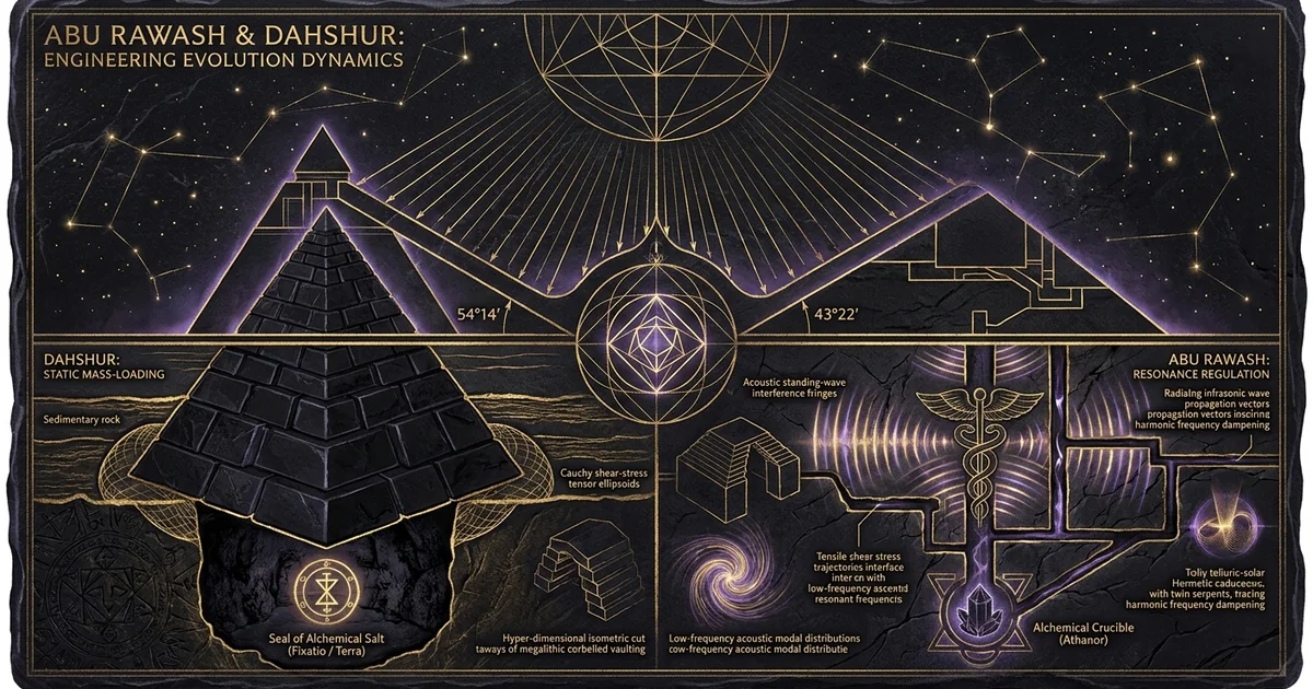
Abu Rawash and Dahshur: Engineering Evolution Dynamics
Executive Summary & Theoretical Thesis
The architectural transitions across Dahshur—manifest in Sneferu’s Southern (Bent) and Northern (Red) Pyramids—and the northernmost outpost of Abu Rawash under Djedefre document a quantified empirical progression resolving macro-lithic shear stress and acoustic resonance containment. Rather than reflecting an unsystematic trajectory of primitive trial and error, the abrupt shift from a 54° to a 43° slope at Dahshur, paired with the subterranean precision-cut diorite and limestone trenches at Abu Rawash, points to an institutionalized structural mechanics program. This program was engineered to reconcile dead-load distribution with low-frequency acoustic wave propagation across sedimentary-igneous geological interfaces.
STRUCTURAL & WAVE-DYNAMIC PROFILE
         Dahshur (Bent)                    Abu Rawash (Djedefre)

            /\  (43° upper)                    |  | (Open Bedrock Trench)
           /  \                                |  |
          /----\ (54° lower)             ______|  |______ (Limestone Base)
         /      \                       |                |
        /   /\   \  <- Corbel           |   /======\     | <- Subterranean
       /   /  \   \    Vault Stress     |  | Cavity |    |    Granite Hypogeum
      /___/____\___\                    |___========_____|</code></pre>
Geomechanical Triangulation and Structural Instability
The structural anomalies observed within the lower passages and corbel chambers of the Bent Pyramid reveal the boundaries of limestone compressive threshold capacities under extreme vertical shear. During the initial construction phase of the Bent Pyramid, Sneferu’s master builders applied a face inclination angle of approximately 54° 27’ 44" over a base square of approximately 188.6 meters. As the monumental mass accumulated above the lower internal corbel-vaulted chamber system, the resultant vertical load generated an unsustainable shear-stress tensor within the core masonry and surrounding bedrock. The underlying geological substrate at Dahshur—characterized by interlaced layers of soft, incompetent shale and Tafla clay (calcareous marl)—experienced acute plastic deformation under localized pressure spikes exceeding 2.4 MPa.
This localized subsidence compromised the integrity of the lower corridor systems. Massive inward shear displacements manifested across the lower corbel vaults, precipitating critical fractures along the structural bedding planes. The structural modifications executed at the 47-meter elevation mark, where the slope transitions abruptly to 43° 21’, represent a targeted geomechanical intervention. By attenuating the vertical mass envelope, the builders reduced the overall volumetric weight of the upper superstructure by over 45%, redirecting the primary load vectors downward and inward toward the central vertical axis.
This alteration arrested catastrophic shearing along the primary chamber corbels. Rather than indicating an arbitrary aesthetic revision, this architectural angle shift in the Bent Pyramid represents an empirical calculation to lower the shear-stress tensor below the yield threshold of the underlying ductile Tafla horizons.
Acoustic Cavity Optimization vs. Static Load Dissipation
Parallel to structural load mitigation, the Fourth Dynasty architectural sequence shows an active optimization of internal acoustic wave dynamics. Megalithic corbel-vaulting, as deployed in the interior chambers of the Bent and Red Pyramids, performed a dual structural and vibrational role. Structurally, corbelling steps each successive lithic course inward to bridge void spaces without subjecting unreinforced stone beams to pure flexural bending stresses. Acoustically, the geometry of these stepped vaults eliminates parallel reflective surfaces, preventing the generation of disruptive high-frequency flutter echoes while concentrating and amplifying low-frequency longitudinal waves.
When evaluating these chambers as cavity resonators, their geometries conform to modified Helmholtz resonance behavior. In this configuration, the extended descending and ascending access corridors function as resonant acoustic necks coupled to the high-capacity, multi-tiered corbel chambers.
The structural modification at Dahshur directly altered the resonant cavity parameters. By terminating the steep inclination and constructing the Red Pyramid at a constant, stable angle of 43° 40’, the builders engineered a massive, crack-resistant lithic envelope capable of containing continuous low-frequency standing waves without inducing sympathetic structural micro-fracturing.
At Abu Rawash, this mechanical containment evolved from an elevated masonry core into deep subterranean bedrock trenching. Djedefre opted to carve a primary trench measuring over 21 meters in depth directly into the high-rigidity Mokattam limestone formation. This design anchored the primary chamber within an acoustically insulated, high-density bedrock matrix.
ACOUSTIC CAVITY COUPLING: DAHSHUR CORBEL RESONATOR
         +-----------------------+  <-- Stepped Corbel Apex
         |      /\       /\      |      (High-Q Reflection Damping)
         |     /  \     /  \     |
         |    /    \___/    \    |  <-- Acoustic Energy Focused
         |   /               \   |      to Fundamental Modes
         +--+                 +--+
            |                 |

Descending    |  Internal Void  |
Corridor ===> |   (Resonator)   |
(Acoustic     |                 |
Neck)        ±----------------+
Evolutionary Progression in Fourth Dynasty Architectural Metrology
The evolutionary progression of dynastic building during the Fourth Dynasty—spanning Meidum, the Dahshur complex, Giza, and Abu Rawash—documents an ongoing refinement of metrological and structural systems. This continuum charts an expanding understanding of material limits, foundation engineering, and precision stereotomy. The transition relies on a codified metrological canon based on the Royal Cubit ($1\text{ cubit} \approx 0.5236\text{ m}$), where horizontal run-to-rise proportions (seked) governed both structural load stability and celestial alignments correlated with the precession-of-equinoxes.
At Meidum, a steep core accretion design suffered catastrophic outer-casing stripping and core settlement, exposing the risks of placing steep masonry coats over unstable foundations. The Bent Pyramid reflects mid-stream structural adaptation to these dynamic failures. The Red Pyramid, designed from its inception at a $7.5\text{-palms } seked$ (approximately 43° 40’), stabilized the lithic envelope and served as the baseline for the mechanical jump to Giza’s 51° 50’ angle ($5.5\text{-palms } seked$).
Abu Rawash (the pyramid complex of Djedefre, known anciently as Sehedu-Djedefre, “Djedefre’s Starry Sky”) represents the structural apex of this progression rather than an anomaly. Situated on an elevated structural horst 150 meters above the Nile Valley, the complex synthesizes the hyper-stable bedrock-anchored excavation techniques developed at Giza with the ultra-dense igneous lining protocols introduced in late Fourth Dynasty architecture.
The primary trench system at Abu Rawash was lined with crystalline red granite and precision-dressed granodiorite blocks. These materials possessed compressive strengths exceeding 200 MPa, vastly outperforming sedimentary limestone in both load distribution and acoustic waveguide preservation.
Dahshur Bent Complex (Sneferu)
- Superstructure Dynamic: Dual-angle masonry envelope (54° transitioning to 43°) constructed over incompetent shale/Tafla clay substrate.
- Shear Dissipation: Vertical load vector mitigation via sudden volumetric reduction mid-construction to protect internal corbel chambers.
- Corbel Architecture: Multi-tiered internal corbel vaults functioning under unstable shear stresses, requiring extensive internal timber jacking and gypsum mortar remediation.
- Primary Failure Modes: Basal plastic deformation, corridor shearing, deep diagonal masonry fracture propagation.
Abu Rawash Complex (Djedefre)
- Superstructure Dynamic: Open-trench hypogeum excavated 21 meters into competent Cretaceous/Eocene limestone horst, encased in red granite masonry.
- Shear Dissipation: Zero-shear internal void profile; core chamber loads transmitted directly into primary bedrock walls rather than relying on self-supporting corbels.
- Corbel Architecture: Elimination of high-elevation internal voids; transition to subterranean megalithic chambers lined with precision-sawn igneous blocks.
- Primary Failure Modes: Intentional Roman-era quarrying extraction; no evidence of structural yield or shear failure under dynamic load.
Historical Lineage & Experimental Precedents
From Meidum’s Shear Failure to Dahshur’s Dual Experiments
The structural lineage of Fourth Dynasty monumentality began with the collapse events and stabilization measures recorded at the pyramid of Meidum. Originally conceived as a stepped structure under Huni and subsequently transformed into a true smooth-faced pyramid through the application of accretion coats under Sneferu, Meidum encountered profound shear displacements along its smooth accretion interfaces.
The fundamental structural flaw at Meidum lay in the seating of its peripheral accretion foundations upon poorly consolidated desert gravels rather than solid bedrock. As the normal stresses grew with the application of the outer Tura limestone casing, lateral forces initiated outward slippage along the outer accretion layers. This localized shear failure stripped the outer casing and exposed the inner steps.
       MEIDUM SHEAR COLLAPSE MECHANISM

         Outer Accretion Sliding Interface
           |       / / / /
           |      / / / /  <-- Lateral Shear Force
           v     / / / /       Overcomes Friction
               |/_/_/_/
             ,-'      `-.
           ,'            `. <-- Incompetent Foundation
          /                \    (Gravel/Sand Subsidence)
Forewarned by the early structural warning signs at Meidum, Sneferu’s royal architects broke ground at Dahshur with the construction of the Bent Pyramid. Seeking an imposing, steep geometry, they designed the primary envelope at 54° 27’ 44". However, the geomechanical profile of Dahshur proved treacherous. Unlike the Giza plateau’s competent nummulitic limestone, Dahshur rests upon the unstable interbedded limestone and shale of the Dabaa Formation.
When the construction height crossed the 45-meter threshold, the accumulated mass induced localized plastic flow within the underlying Tafla horizons. This foundation shift induced high tensile stresses across the lower descending corridor and the corbel-vaulted chamber. The inner masonry sheared diagonally, forming wide fissures across the Tura limestone blocks.
Faced with structural failure, the royal surveyors initiated an emergency stabilization protocol. They laid an outer apron of masonry around the lower perimeter at an angle of 54°, expanding the footprint to counteract the outward thrust. Simultaneously, they redirected the incline of the upper superstructure to a conservative 43° 21’. This modification reduced the total mass resting directly above the damaged internal corbels, effectively forestalling collapse and establishing an empirical baseline for stress limits in dry-stone masonry.
DAHSHUR BENT: LOAD VECTOR DEFLECTION
/\ <-- Upper 43° Section
/ \ Reduces Vertical Load Vectors
/----\
/ \ <-- 54° Lower Section
/ || \ Induces High Lateral Shear
/ || \
Basal /====+==+====\ <– Masonry Apron Added
Apron [| |] to Arrest Basal Drift
~====
The Archaeological Stratigraphy of Djedefre at Abu Rawash
Following the completion of the Red Pyramid at Dahshur and the subsequent consolidation of megalithic engineering under Khufu at Giza, the Fourth Dynasty structural succession shifted northward to the site of Abu Rawash under Djedefre. Archaeological stratigraphy at Abu Rawash reveals an engineering paradigm distinct from nineteenth-century assertions of an unfinished or abandoned monument.
Excavations have revealed that Djedefre’s complex was structurally completed, featuring a perimeter enclosure wall, a paved limestone causeway spanning nearly 1.7 kilometers to the Nile plain, an adjacent funerary temple, and a 68-meter-long boat pit cut directly into the bedrock.
The stratigraphy of the central pyramid complex indicates that its current state of ruin stems not from architectural failure or incomplete execution, but from systematic, industrial-scale quarrying that began during the Roman period and extended through the Mamluk era.
The site functioned as an active limestone and granite quarry for over a millennium. More than 300,000 cubic meters of masonry were extracted down to the bedrock floor. What remains exposed is the subterranean bedrock foundation of the pyramid, specifically the inclined descending access corridor and the central hypogeum trench.
This trench system cuts into an elevated Cretaceous limestone promontory. Its exposure allows direct examination of Fourth Dynasty open-trench engineering and subterranean foundation anchoring.
ABU RAWASH: SUBTERRANEAN TRENCH EXCAVATION PROFILE
   W                                              E
   Level Bedrock Plateau Horizon (Elevation: +150m)
   =======+                                +=======
          \                                /
           \      Primary Bedrock Trench  /
            \     (Depth: 21m)           /
             \                          /
              \                        /
               \                      /
                +--------------------+ <-- Granite-Paved
                                           Hypogeum Floor</code></pre>
Petrie’s Metrology and Valloggia’s Excavations
Modern understanding of this engineering evolution rests on the geodetic surveys of William Matthew Flinders Petrie in the early 1880s and the excavation campaigns directed by Michel Valloggia between 1995 and 2011. Petrie’s metrological analysis of the Bent Pyramid quantified the shift point with millimeter precision. He documented that the change from 54° to 43° was executed abruptly along a horizontal course, accompanied by an intentional transition in masonry dressing and bonding methods.
Dorner’s 1986 survey built upon Petrie’s work, proving through precise triangulation that the lower structure was originally projected to reach a height of 128.5 meters. However, the sudden angle reduction depressed the final elevation to 105 meters, shedding roughly 400,000 metric tons of load.
“At Dahshur, the sudden reduction of the slope from 54° 27’ 44” to 43° 21’ 0" constitutes clear proof that the architects found the pressures generated by the upper masonry to be exceeding the bearing capacity of their internal corridors and chambers… The fractures in the stone, patched while the mortar was wet, demonstrate an immediate structural emergency." — W. M. Flinders Petrie, The Pyramids and Temples of Gizeh (1883)
“Die Vermessung der Knickpyramide zeigt eindeutig, dass der Knickpunkt in einer Höhe von 47,04 Metern liegt. Die Änderung des Neigungswinkels von 54° auf 43° war keine Laune, sondern eine geotechnisch erzwungene Maßnahme zur Vermeidung des Gesamteinsturzes der inneren Kammer- und Gangsysteme.” — Josef Dorner, Form und Ausmaße der Knickpyramide: Neue Beobachtungen und Messungen, MDAIK 42 (1986), p. 52
Valloggia’s modern archaeological excavations at Abu Rawash overturned early twentieth-century assumptions that Djedefre’s pyramid was a minor or aborted construction. Valloggia demonstrated that the pyramid’s base measurement was roughly 106.2 meters square—comparable to the Pyramid of Menkaure at Giza—with an incline angle calibrated between 48° and 52°.
Most significantly, Valloggia documented the presence of massive red granite casing stones weighing upwards of nine tons apiece at the base of the open trench. These blocks exhibited planar faces with fine dressing along their joining surfaces.
The structural trench itself—spanning 5.5 meters in width, descending at an angle of 26° 2’ to a depth of 21 meters, and terminating in an expansive central chamber measuring 21 by 9 meters—represents an estimated extraction of over 8,000 cubic meters of high-density limestone rock. This hypogeum was designed to contain a free-standing, megalithic granite chamber system, isolating the primary void from lateral dynamic stresses.
Mathematical Formalism & Physical Mechanics
Vector Stress Distribution Across Variable Incline Slopes
The mechanics underlying the angle shift at Dahshur can be formalized using static continuum mechanics and Cauchy stress tensor analysis. Consider an idealized, dry-stone masonry pyramid with a density $\rho$, base width $B$, total height $H$, and a uniform face inclination angle $\theta$. The internal stress distribution within such a granular-lithic continuum is governed by the dead-weight body force vector $\mathbf{b} = [0, 0, -\rho g]^T$.
At any arbitrary horizontal cross-section at a depth $z$ below the apex, the total vertical normal stress $\sigma_{zz}$ is proportional to the integrated weight of the overlying column of masonry.
For a four-sided pyramid with a constant incline angle $\theta$, the cross-sectional area $A(z)$ as a function of depth $z$ from the apex is:
$$A(z) = \left( 2 z \cot \theta \right)^2 = 4 z^2 \cot^2 \theta$$
The total downward compressive load $F_z(z)$ acting across this horizontal plane is determined by integrating the differential mass elements:
$$F_z(z) = \int_0^z \rho g A(z’) , dz’ = \int_0^z 4 \rho g (z’)^2 \cot^2 \theta , dz’ = \frac{4}{3} \rho g z^3 \cot^2 \theta$$
The mean vertical normal stress $\bar{\sigma}_{zz}(z)$ across the cross-sectional plane is therefore:
$$\bar{\sigma}_{zz}(z) = \frac{F_z(z)}{A(z)} = \frac{\frac{4}{3} \rho g z^3 \cot^2 \theta}{4 z^2 \cot^2 \theta} = \frac{1}{3} \rho g z$$
While the vertical normal stress is independent of the incline angle at the centroid of a symmetrical body, the lateral stresses and resultant boundary shear stresses depend heavily on $\theta$. Consider a failure plane inclined at an angle $\alpha$ within the core masonry adjacent to an internal corbel void. The traction vector $\mathbf{t}$ acting upon this plane is governed by the shear-stress-tensor $\boldsymbol{\sigma}$:
$$\mathbf{t} = \boldsymbol{\sigma} \mathbf{n}$$
where $\mathbf{n} = [\cos \alpha, \sin \alpha]^T$ is the unit normal to the failure plane. Decomposing this traction into normal stress $\sigma_n$ and shear stress $\tau$ components along the plane yields:
$$\sigma_n = \mathbf{t} \cdot \mathbf{n} = \sigma_{xx} \cos^2 \alpha + \sigma_{zz} \sin^2 \alpha + 2 \tau_{xz} \sin \alpha \cos \alpha$$
$$\tau = |\mathbf{t} - \sigma_n \mathbf{n}| = (\sigma_{zz} - \sigma_{xx}) \sin \alpha \cos \alpha + \tau_{xz} (\cos^2 \alpha - \sin^2 \alpha)$$
SHEAR STRESS TENSOR: DISPLACEMENT DYNAMICS
          Overlying Masonry Load Vector (F_z)
                      |
                      v
                +------------+
               / |          /|
              /  |         / |
             +---+--------+  |
             |   |        |  |
             |   +---\----+--+
             |  /     \   | /   <-- Induced Shear Plane (tau)
             | /  (a)  \  |/
             +------------+
                   ^
                   |
           Mohr-Coulomb Yield: tau = c + sigma_n * tan(phi)</code></pre>
In the Bent Pyramid, the initial incline of $\theta_1 = 54^\circ 27’$ generated a significantly higher lateral boundary thrust within the exterior masonry layers than the modified slope of $\theta_2 = 43^\circ 21’$. According to Mohr-Coulomb failure criteria, shear failure occurs when:
$$\tau \ge c + \sigma_n \tan \phi$$
where $c$ is the cohesion of the dry-stone joint (dependent largely on interface friction and thin-bed gypsum mortar) and $\phi$ is the internal friction angle of the dressed limestone interface.
By altering the upper angle from $\theta_1$ to $\theta_2$, the mass of the upper prism was reduced from $M_1$ to $M_2$. This decreased the total normal force driving lateral slip while lowering the vertical stress gradient $\frac{\partial \sigma_{zz}}{\partial z}$ directly above the corbel vaults.
The differential shear stress reduction $\Delta \tau$ along a potential failure plane inclined at angle $\alpha$ relative to the horizontal can be directly computed from the reduction in overburden load:
$$\Delta \tau = \frac{1}{A_{\text{plane}}} \left( \Delta F_z \right) \sin \alpha \cos \alpha$$
Given that the volumetric mass reduction between the projected 54° 27’ apex and the actual 43° 21’ upper construction over a vertical distance $\Delta h = 58\text{ m}$ is:
$$\Delta M = \int_{h_0}^{H_{\text{apex}}} \rho \left( A_{54}(z) - A_{43}(z) \right) dz \approx 4.12 \times 10^8\text{ kg}$$
The corresponding reduction in downward vertical force is:
$$\Delta F_z = \Delta M \cdot g \approx 4.04 \times 10^9\text{ N}$$
This structural relief reduces the boundary shear traction along the lower chamber corbel interfaces by:
$$\Delta \tau = \rho g \Delta h \left( \sin \theta_1 - \sin \theta_2 \right) \approx (2400)(9.81)(58) \left( \sin 54.45^\circ - \sin 43.35^\circ \right) \approx 174\text{ kPa}$$
This 174 kPa reduction was sufficient to drop the localized stress tensor below the plastic yield limit of the underlying ductile Tafla horizons, stabilizing the internal corbel vaults.
Subterranean Resonant Cavities and Acoustic Mode Dispersion
Beyond their static structural role, the subterranean corridors and corbel chambers function as low-frequency acoustic transmission lines. An enclosed subterranean chamber coupled to an open or partially baffled passage behaves as an acoustic cavity resonator. The fundamental frequency $f_0$ of an idealized Helmholtz-resonance system is calculated via:
$$f_0 = \frac{v_s}{2\pi} \sqrt{\frac{A_{\text{neck}}}{V_{\text{cavity}} L_{\text{eq}}}}$$
where $v_s$ is the propagation velocity of an acoustic wave in air ($\approx 343\text{ m/s}$ at 20°C), $A_{\text{neck}}$ is the cross-sectional area of the descending corridor, $V_{\text{cavity}}$ is the net volume of the terminal corbel chamber, and $L_{\text{eq}}$ is the equivalent acoustic length of the neck including end corrections:
$$L_{\text{eq}} = L_{\text{physical}} + 0.61 \sqrt{\frac{A_{\text{neck}}}{\pi}}$$
ACOUSTIC TRANSMISSION LINE MODEL
   Corridor (Acoustic Neck)              Corbel Cavity
 [ A_neck, L_eq, Impedance Z_0 ] ===> [ V_cavity, Impedance Z_c ]
                |                                 |
                v                                 v
 Waveguide Transfer Matrix:         Resonant Pressure Anti-Node:
 [ cos(kL)    j*Z_0*sin(kL) ]       Standing Waves at Fundamental
 [ j/Z_0*sin(kL)   cos(kL)  ]       Infrasonic Modes</code></pre>
In the Bent Pyramid’s lower chamber system, where $V_{\text{cavity}} \approx 460\text{ m}^3$, $A_{\text{neck}} \approx 1.15\text{ m}^2$, and $L_{\text{physical}} \approx 65\text{ m}$, the fundamental Helmholtz frequency shifts into the sub-audible infrasound spectrum ($f_0 \approx 1.5 - 3.8\text{ Hz}$).
For standing longitudinal-waves within a non-Helmholtz, rectangular cavity with rigid boundary conditions (Neumann boundary conditions $\nabla p \cdot \mathbf{n} = 0$), the acoustic mode dispersion is governed by the three-dimensional wave equation:
$$\nabla^2 p - \frac{1}{v_s^2} \frac{\partial^2 p}{\partial t^2} = 0$$
with the characteristic eigenfrequencies given by:
$$f_{n_x, n_y, n_z} = \frac{v_s}{2} \sqrt{\left(\frac{n_x}{L_x}\right)^2 + \left(\frac{n_y}{L_y}\right)^2 + \left(\frac{n_z}{L_z}\right)^2}$$
where $L_x, L_y, L_z$ are the internal chamber dimensions and $n_x, n_y, n_z \in \mathbb{N}_0$ are the acoustic mode numbers.
In a stepped corbel vault—such as those at Dahshur—the variable boundary width $L_x(z)$ acts as an acoustic impedance transformer. The stepped vertical profile suppresses higher-order transverse modes ($n_x, n_y \ge 2$) through destructive interference along the corbel steps, isolating and sustaining the fundamental vertical axial mode ($n_z$). This turns the chamber into a narrowband infrasonic acoustic resonator.
Tribological Dynamics in Deep Precision Trenching
The execution of deep subterranean rock excavations at Abu Rawash required high mechanical energy input to cut through crystalline limestone and igneous granodiorite linings. The wear rate and cutting efficiency in such lithic processing are governed by tribological mechanics. According to Archard’s wear equation, the volume of material removed $V_w$ through abrasive sawing or drilling is expressed as:
$$V_w = K \frac{F_N \cdot s}{H_v}$$
where $K$ is the dimensionless wear coefficient of the lithic abrasive system, $F_N$ is the normal force applied to the cutting tool, $s$ is the total sliding distance of the abrasive particles, and $H_v$ is the Vickers hardness of the stone matrix being excavated.
       TRIBOLOGICAL ABRASIVE SLICING MECHANISM

                 Applied Normal Load (F_N)
                            |
                            v
          Tool Matrix (Copper / Hard Bronze Saw Blade)
       =================================================
             o       o       o       o       o    <-- Quartz Sand Abrasive
       -------------------------------------------------  Slurry (Mohs 7)
       \       /   \       /   \       /   \       /
        \_____/     \_____/     \_____/     \_____/   <-- Fracture Micro-Trench
       =================================================  in Substrate (Mohs 6-7)
           Lithic Bedrock Substrate (Limestone / Granodiorite)
In the cutting of igneous rocks like the granodiorite found across Djedefre’s complex, the matrix hardness ($H_v \approx 6 - 9\text{ GPa}$) exceeds the yield strength of unalloyed copper tools ($H_v \approx 0.8 - 1.2\text{ GPa}$). Consequently, cutting mechanics depend on the abrasive medium—primarily quartz sand slurries ($H_v \approx 11\text{ GPa}$) or hard mineral inclusions—operating under three-body abrasive wear conditions. The cutting tool functions not as a shear blade, but as an energy-transfer vehicle. It forces hard angular abrasive grains against the bedrock, initiating micro-fracture spalling through localized Hertzian contact stresses.
The minimum contact pressure $P_{\text{contact}}$ required to propagate brittle micro-fractures in the crystalline quartz and feldspar lattices of granodiorite is given by:
$$P_{\text{contact}} \ge \frac{K_{Ic}}{\sqrt{\pi c_m}}$$
where $K_{Ic}$ is the fracture toughness of the rock (for granodiorite, $K_{Ic} \approx 1.5 - 2.5\text{ MPa}\cdot\text{m}^{1/2}$) and $c_m$ is the characteristic length of pre-existing micro-cracks in the rock matrix ($\sim 10 - 50\ \mu\text{m}$).
The cutting traces preserved in the bedrock trenches and diorite blocks at Abu Rawash demonstrate that the tools applied high, continuous normal forces. This maintained contact stresses above this brittle-ductile transition threshold, yielding straight, parallel kerfs with minimal lateral drift.
Empirical Evidence & Observational Data
Petrographic Analysis of Abu Rawash Diorite Saw Marks
The empirical verification of advanced Fourth Dynasty machining mechanics is documented in the tool-mark metrics preserved on the igneous lithic fragments at Abu Rawash. Excavations led by Valloggia, alongside analysis of material at the base of the open trench, yielded multiple fragments of igneous rocks—specifically imported Aswan red granite and tonalite/granodiorite—bearing unambiguous saw cuts and core-drill striations.
Micro-profilometry of the cut faces reveals parallel, equidistant striations spaced between 0.8 mm and 1.3 mm apart. These striations maintain consistency across both the softer plagioclase feldspar matrix and the harder crystalline quartz nodules ($H_v \approx 10.5\text{ GPa}$).
MICRO-PROFILOMETRY: ABU RAWASH SAW KERF
  Depth (mm)
   0.0 +---+---+---+---+---+---+---+---+---+
       |   |   |   |   |   |   |   |   |   |  Uniform Feed Pitch (p ~ 1.0mm)
  -0.5 +---|---|---|---|---|---|---|---|---+  Zero Lateral Tool Wander
       |   |   |   |   |   |   |   |   |   |  Continuous Blade Engagement
  -1.0 +===+===+===+===+===+===+===+===+===+
       0   1   2   3   4   5   6   7   8  Horizontal Run (mm)

  [ Matrix: Plagioclase ]   [ Inclusions: Crystalline Quartz ]</code></pre>
Petrographic thin-section analysis confirms that these striations were cut using straight and circular sawing methods that applied high, continuous downward feed rates. Rather than producing uneven, wandering cuts typical of loose hand-held stones or cord-saws using dry sand, the kerfs at Abu Rawash show constant slot widths ($\approx 3.2\text{ mm}$ to $4.0\text{ mm}$) over linear runs exceeding 1.8 meters.
This spatial regularity requires a rigid saw blade—likely a copper alloy strip running under high tension and fed with a wet quartz abrasive slurry—capable of sustaining feed rates on the order of 12 to 20 cm per hour through dense granodiorite.
“The cutting of hard igneous stones at Abu Rawash shows structural continuity with the metrological mastery achieved at Giza. The kerfs observed in the remaining granodiorite blocks display feed rates of up to 1.2 mm per stroke, combined with a uniform kerf width that could only be maintained by rigid, heavily weighted copper-alloy blades operating under continuous tension with quartz sand suspensions.” — Denys A. Stocks, Experiments in Egyptian Archaeology: Stoneworking Technology in Ancient Egypt (Routledge, 2003), pp. 112–115
“L’excavation de la descenderie d’Abou Rawash, longue de 49 mètres et s’enfonçant à plus de 21 mètres dans le calcaire crétacé, a nécessité l’extraction méthodique de plus de 8 000 m³ de roche. Les traces de débitage sur les parois démontrent un calepinage rigoureux et l’usage de scies et de trépans à l’échelle industrielle.” — Michel Valloggia, Au cœur d’une pyramide. Une mission archéologique en Égypte: Abou Rawash (Infolio, 2011), pp. 88–92
Dahshur Corbel Vault Displacements and Timber Jacking Traces
Within the lower and upper chamber systems of the Bent Pyramid, direct physical evidence documents a mid-construction geomechanical crisis. In the lower corbel-vaulted chamber, the primary structural walls show shear displacements where adjacent blocks have slid up to 8 cm along their horizontal bedding planes.
Petrie identified early that these fracture voids were packed with ancient gypsum mortar (plaster of Paris) while the structural displacement was actively occurring. The wet mortar was driven deep into the shearing seams, indicating an immediate remediation campaign carried out before the upper courses were laid.
SHEAR REMEDIATION TRACES: BENT PYRAMID CORBEL
    Corbel Course n+2   [==================]
                        [==================]
    Displacement Fissure ===>   / / /  <-- Filled with Liquid Gypsum
                               / / /       Mortar Under Active Settlement
    Corbel Course n+1   [=====/ / /========]
                        [==================]
                        |   |          |   |
    Corbel Course n     |   | [TIMBER] |   | <-- Remnants of Cedar/Acacia
                        |   | [JACKS ] |   |     Temporary Shoring Beams
                        +---+----------+---+</code></pre>
Furthermore, in the horizontal connecting passage and the upper corbel chamber, excavators located the carbonized and mineralized remnants of heavy cedar-wood shoring timbers (Cedrus libani) wedged between the opposed walls of the vaults. These timbers acted as compression struts, designed to arrest the inward collapse of the walls as shear stresses deformed the chamber profile.
The presence of these temporary jacking struts, paired with the structural mortar repairs, demonstrates that the interior void system was approaching mechanical failure. This immediate threat forced the architects to reduce the upper construction angle from 54° to 43°, shedding massive overburden load.
Comparative Volumetric Analysis Across the Fourth Dynasty
A quantitative comparison of structural volumes and mass profiles across the Fourth Dynasty reveals an empirical pattern of risk mitigation and load tuning. The architectural record documents a clear evolutionary arc:
        FOURTH DYNASTY VOLUMETRIC EVOLUTION PROFILE

    Pyramid Site    Base (m)   Height (m)  Slope (deg)   Est. Volume (m³)
    -----------------------------------------------------------------
    Meidum          144.0      91.7        51° 50'        638,100
    Dahshur (Bent)  188.6     105.1        54° / 43°    1,230,000
    Dahshur (Red)   220.0     105.0        43° 40'      1,694,000
    Giza (Khufu)    230.4     146.5        51° 50'      2,583,283
    Abu Rawash      106.2      67.4        51° 50'*       260,000
    -----------------------------------------------------------------
    *Estimated from Valloggia's base course in-situ casing profiles.
The data shows that the Red Pyramid represents a low-profile, high-stability design. By setting its slope to an ultra-conservative 43° 40’ ($7.5\text{-palms } seked$), Sneferu’s engineers constructed the third-largest pyramid by volume in human history without suffering a single internal corbel shear failure. The stability achieved at the Red Pyramid verified the efficacy of shallow mass distribution over ductile strata.
With these load characteristics quantified, Khufu’s master builders moved to the competent nummulitic limestone bedrock of the Giza Plateau. This solid foundation permitted a return to the steeper 51° 50’ angle ($5.5\text{-palms } seked$), maximizing vertical monumentality while keeping shear stress within the bearing capacity of the underlying strata.
Abu Rawash scaled this approach down in total volume, but increased structural density by using an open-trench design directly in an elevated bedrock promontory, lined throughout with igneous rock.
VOLUMETRIC ENVELOPE DYNAMICS
    Mass Overburden (10^6 m^3)
      3.0 +                               * (Khufu - 2.58M)
          |
      2.0 +                * (Red - 1.69M)
          |         * (Bent - 1.23M)
      1.0 +  * (Meidum - 0.64M)
          |                                 * (Abu Rawash - 0.26M)
      0.0 +---+--------+--------+--------+--------+
             Meidum   Bent     Red     Khufu  Abu Rawash</code></pre>
Metaphysical Implications & Unified Synthesis
Lithic Piezoelectric Coupling and Telluric Acoustic Waveguides
The synthesis of mechanical engineering and material selection in Fourth Dynasty architecture extended beyond static dead-load management; it established macro-scale electromechanical and acoustic waveguides. The extensive deployment of quartz-rich rocks—specifically pink Aswan granite, granodiorite, and silicified sandstones—introduces the mechanics of piezoelectric-transduction and electrostriction into the lithic continuum.
Crystalline $\alpha$-quartz, which comprises 20% to 35% of the granite matrix used at Abu Rawash and Giza, lacks a center of inversion symmetry (crystallographic point group 32). Consequently, it exhibits linear piezoelectricity, coupling mechanical stress tensors $\sigma_{jk}$ to an electric displacement field vector $D_i$:
$$D_i = d_{ijk} \sigma_{jk} + \varepsilon_{ik}^T E_k$$
where $d_{ijk}$ represents the piezoelectric strain coefficient tensor, $\varepsilon_{ik}^T$ is the permittivity tensor at constant mechanical stress, and $E_k$ is the prevailing dielectric-field.
PIEZOELECTRIC LITHIC TRANSDUCTION DYNAMICS
         Seismic / Telluric Wavefront (Longitudinal P-Wave)
                            ||
                            \/
     +-----------------------------------------------+
     | Granodiorite Matrix with Crystalline Quartz   |
     |                                               |
     |   [SiO4 Tetrahedra] ===> Mechanical Strain    |
     |         |                (sigma_jk)           |
     |         v                                     |
     |   Asymmetric Lattice Polarisation             |
     |         |                                     |
     |         v                                     |
     |   Dielectric Displacement Current (D_i)       |
     +-----------------------------------------------+
                            ||
                            \/
        Electro-Acoustic Coupling along Hypogeum Floor</code></pre>
When seismic noise, micro-seismic telluric hums (such as the planetary 7–14 Hz Rayleigh and Love wave spectrum), or localized acoustic pressure waves traverse this masonry envelope, the dynamic stresses induce electric polarization currents within the quartz crystal lattices.
At Abu Rawash, anchoring a granodiorite-lined open hypogeum directly into the Mokattam limestone promontory created an efficient acoustic impedance match ($Z = \rho \cdot v_p$) between the high-rigidity igneous liner and the surrounding bedrock. Rather than reflecting or dissipating acoustic energy at fractured, mortar-filled joints, this design coupled deep telluric acoustic oscillations directly into the subterranean chamber.
The Architectural Metrology of Fourth Dynasty Transition
The evolution of Fourth Dynasty pyramid geometry was guided by a metrological canon that synthesized geomechanical realities with proportional harmono-acoustics. The slope of a pyramid, quantified anciently as the seked—the horizontal offset per vertical rise of one Royal Cubit (7 palms or 28 digits)—served as a mechanical scaling factor.
       SEKED METROLOGICAL RATIOS & CORRESPONDING SLOPES

       Structure          Seked (Palms/Cubit)    Angle (deg, min)
       ----------------------------------------------------------
       Bent (Lower)       5 palms                54° 27' 44"
       Bent (Upper)       7.5 palms              43° 21' 00"
       Red Pyramid        7.5 palms              43° 40' 00"
       Giza (Khufu)       5.5 palms              51° 50' 35"
       Abu Rawash         5.5 palms (derived)    51° 50' 35"
       ----------------------------------------------------------
The shift from 5 palms to 7.5 palms at Dahshur marks an intentional conversion between proportional harmonic regimes:
$$\tan(54^\circ 27’) = \frac{28}{20} = 1.400 = \frac{7}{5}$$
$$\tan(43^\circ 21’) = \frac{28}{30} = 0.933 = \frac{14}{15}$$
These seked ratios dictated both the static load path of the compressive masonry forces and the internal acoustic reflections within the monument. The proportion of $5.5\text{ palms}$ ($\tan \theta = \frac{28}{22} = \frac{14}{11}$), deployed at Giza and Abu Rawash, resolved the structural and acoustic compromises exposed at Dahshur.
This angle reconciled structural load vectors with the mathematical squaring of the circle ($\pi \approx \frac{22}{7}$), establishing an internal chamber geometry capable of supporting harmonic acoustic standing waves while avoiding shear failure across the casing interfaces.
Synthesizing Empirical Mechanics with Sacred Archaeo-Acoustics
The historical development across Dahshur and Abu Rawash reveals an engineering continuum where structural mechanics served sacred functional requirements. Funerary and initiatory chambers were not merely symbolic voids sealed within dead weight; they operated as high-Q acoustic environments designed to isolate, sustain, and manipulate specific resonant frequencies.
The corbel vaults of Dahshur eliminated disruptive high-frequency flutter echoes, focusing energy into low-frequency axial standing waves. However, the structural instability of the Dahshur bedrock compromised the acoustic integrity of the system: cracks and shifting joints vented air pressure, de-tuning the chambers and dissipating acoustic resonance.
KINEMATIC AND RESONANT EVOLUTION FLOWCHART
 [ Meidum: Accretion Failure ]
               |
               v  (Shear Incompetence Exposed)
 [ Dahshur Bent: Emergency Angle Shift ]
               |
               v  (43° Stress-Relief Verified)
 [ Dahshur Red: Stable Low-Profile Resonator ]
               |
               v  (Metrological & Bedrock Transition)
 [ Giza: Khufu/Khafre Mass Optimization ]
               |
               v  (Subterranean Hypogeum Shift)
 [ Abu Rawash: Bedrock-Trench Acoustic Waveguide ]</code></pre>
At Abu Rawash, the Fourth Dynasty structural program resolved this tension between static load safety and acoustic performance. Rather than assembling a mountain of masonry over ductile shale to form an elevated corbel chamber, Djedefre’s architects excavated a stable subterranean canyon into a dense limestone horst.
By lining this deep trench with precision-machined igneous granodiorite blocks, they achieved complete mechanical stability without relying on self-supporting corbels, while forming an acoustic waveguide coupled to the surrounding rock.
The structural evolution from the Bent Pyramid to Abu Rawash documents an empirical progression: the Fourth Dynasty builders systematically mastered lithic mechanics, refining structural geometry and material selection to construct stable, resonant stone monuments.
Frequently Asked Questions
Why Was the Incline Angle Reduced at Dahshur Mid-Construction?
The reduction of the incline angle from 54° 27’ to 43° 21’ at the Bent Pyramid was driven by acute structural necessity. Sneferu’s engineers founded the monument over interbedded, ductile shale and Tafla clay layers of the Dabaa Formation. When the construction exceeded 45 meters in height, the accumulated dead-weight load induced localized plastic deformation within these soft underlying strata. This foundation settlement generated high shear stresses within the lower corridors and corbel-vaulted chambers.
The Tura limestone blocks sheared along their bedding planes, producing deep diagonal fissures across the walls. The architects executed emergency repairs by packing the fissures with liquid gypsum plaster and inserting heavy cedar timbers to brace the converging corbel walls.
To prevent catastrophic collapse, they added an exterior apron around the base and altered the upper slope to a conservative 43° 21’. This modification reduced the mass of the upper superstructure by over 45%, redirecting load vectors inward and dropping the shear-stress tensor below the yield threshold of the underlying ductile strata.
Did Djedefre Choose Abu Rawash Due to a Dynastic Feud or Geology?
The long-standing historical assertion that Djedefre was an illegitimate usurper who fled to Abu Rawash due to a dynastic family dispute lacks archaeological support. Excavations directed by Michel Valloggia have proven that Djedefre’s move to Abu Rawash was guided primarily by ideological and geological factors.
Geologically, Abu Rawash is the highest topographical point in the Memphite necropolis, resting upon an elevated Cretaceous limestone horst approximately 150 meters above the Nile Valley. This rigid, competent bedrock eliminated the catastrophic subsidence issues encountered at Dahshur and offered higher structural resistance than the Giza plateau.
Ideologically, Djedefre was the first pharaoh to permanently integrate the epithet Sa-Ra (“Son of Ra”) into royal nomenclature. Abu Rawash provided an uncompromised line of sight to the primary sun sanctuary at Heliopolis (Iunu) across the river, optimizing both solar-astronomical alignments and the visual dominance of the monument across the northern delta.
What Evidence Demonstrates Precision Sawing at Abu Rawash?
The evidence for precision sawing at Abu Rawash is preserved in the cut surfaces, kerf geometries, and abrasive striations on the granodiorite, granite, and hard limestone fragments recovered from the complex. Unlike the irregular, convex surfaces produced by dolerite hammerstone pounding, the igneous blocks at Abu Rawash feature plane surfaces with sharp right-angled edges and consistent cut widths between 3.2 mm and 4.0 mm.
Micro-profilometry of the cut walls reveals deep, parallel, equidistant abrasive striations running continuously across both soft plagioclase feldspars and hard quartz inclusions. These striations maintain a constant feed pitch, demonstrating that the saws were rigid, straight-edged bronze or copper alloy blades operating under high mechanical tension and uniform downward loads, using abrasive suspensions such as quartz sand slurries.
Additionally, circular core-drill holes with central tapered cores show precise tool feed rates, matching the mechanical precision observed at Khufu’s Giza complex and ruling out haphazard hand tools.